This thread has been locked.

If you have a related question, please click the "Ask a related question" button in the top right corner. The newly created question will be automatically linked to this question.

TCA4307: Can I place the i2c hot swap buffer on the "backplane"?

Part Number: TCA4307

Hi,

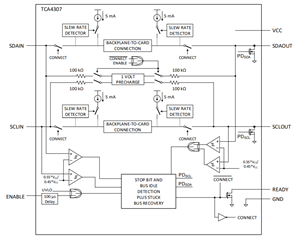
I'd like to use something like the TCA4307 to support hot swap on an i2c bus.

I notice in the datasheet that it is most normal to place this device on the removable peripheral card, however I would prefer to avoid that for space and simplicity reasons. The card in question has only a single device and little-to-no other circuitry.

In the datasheet under "Design Requirements" it states "It is NOT recommended to place the TCA4307 on the backplane connector as it cannot isolate the cards from one another which will possibly result in disturbing on-going I2C transactions."; but I read this to mean "do not place a TCA4307 on the backplane and share it with multiple peripheral cards", which is not what I propose.

In the app note scpa058, it suggests using an i2c switch and GPIOs to detect inserted cards, but I'd prefer to avoid the added (software) complexity.

Is there any reason I cannot use the TCA4307 on the backplane following the approach below:

  • one permanently powered TCA4307 on the backplane per peripheral card.
    • avoids contention between cards.
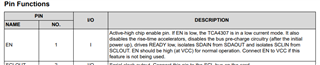
  • using the enable pin to only enable the device when the card "presence" pin has connected.
    • maintains isolation between in and out until the card is ready.
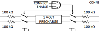
    • the "presence" pin would be designed to mate either first or last upon insertion. I suppose first would allow the pre-charge to be ready.

?

Alternatively, are there any other recommended methods which would allow me to keep an absolute minimum of components on the peripheral card?

Many thanks.

  • This would work. You should not try to enable the buffer before all signals of the card have been connected.

    If you need hot swapping, and do not want to handle this in software, then you need this buffer.

  • Hi Clemens, thanks for the quick & clear response.

    Enabling the buffer only after all signals are connected is easier for me, so that's good. But will it mean that I miss out on the pre-charge behaviour?

    I'm looking at the functional block diagram here and I don't really understand what is meant by the combined AND/OR symbol. Can you explain what that symbol means please?

    If it works like an OR, then I suppose I get the pre-charge even if ENABLE is low, because CONNECT will be low.

    Thank you.

  • If I interpret the description in the datasheet correctly, the pre-charge always happens at power up, even if ENABLE is low.

  • I think I see what you're getting at. Taking a look at the Pin Functions table it states that the pre-charge circuitry is active during initial power up.

    But after initial power up, if the enable pin is low then the pre-charge is disabled, so that's no good - at least not for the application I'm proposing where the TCA4307 is on the backplane and permanently powered.

    Thanks again.

  • Can you change the card connector so that the buffer is powered with a trace that is connected through the card?

  • That's a good idea - thanks. It sounds like that achieves the buffer effectively behaving as though it is on the card.

    I could probably either loop power via the connector, or use a "presence" signal pin to toggle power to the buffer via a FET.

    So I think this is what happens:

    • On card insertion, buffer is powered as soon as possible (early-mating connector pins).
    • ENABLE is tied high, so pre-charge immediately becomes active until connection.
    • Shortly afterwards, the i2c signals from the card mate and connection is ready to be made once the bus is idle.