This thread has been locked.

If you have a related question, please click the "Ask a related question" button in the top right corner. The newly created question will be automatically linked to this question.

TFP401A: HDMI diff pairs series capacitors

Part Number: TFP401A
Other Parts Discussed in Thread: DM388

Hi,
We are developing a device with 1920x1080 60Hz LCD panel and TMS320DM388 processor now.

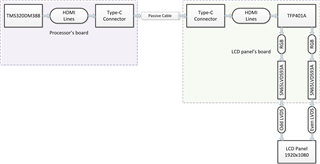
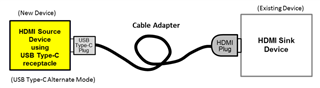
Type-C connectors and USB cable is used for transfer HDMI signals from processor’s board to LCD panel's board. I have a question about AC-couple capacitors on high speed TMDS differential pairs (3xData and 1xClock). Did I should to set 0,1uF capacitors on high speed lines? Did I should place capacitors on host o device side if needed? I use ESD protection IC (TPD12S016PW) on host and slave sides and ferrite differential filters DLP11SA900HL2B on both side now. Is this approach is correct?
Regards, Maxim

  • Hi, Maxim

    HDMI is a 3.3V DC-coupled interface.

    On the TMS320DM388 side, you can reference to this app note on driving HDMI over Type-C, https://www.ti.com/lit/an/slla333/slla333.pdf

    On the TFP401A, you can't use Type-C connector as the implementation is not supported by the HDMI Alt Mode over Type-C. It has to be HDMI as shown below.

    For Type-C, you would also need a PD controller that can support HDMI Alt Mode on the TMS320DM388 side. 

    Thanks
    David

  • Hi, David
    I am not use USB alt mode. It's not needs in our application. I am using only USB cable in fixed position with two type-c connectors inside device case. USB connectors and cable placed inside our devices case and user haven't access them. We aren't use redriver and crosspoint switch. We using that connection like a common cable with single wires and differential pairs.
    Regards, Maxim

  • Maxim

    In this case, why not just DC-couple everything since HDMI is a 3.3V DC-coupled interface? What is the reason for going AC-coupling?

    Thanks

    David

  • Hi, David
    I thought serial capacitors exclude potential possibility of through currents occurrence at powers up time between two boards (processor board and LCD panel board) in our case.
    Regards, Maxim

  • Maxim

    Both the DM388 and TFP410A are designed to be HDMI/DVI compliant which requires the interface to be DC-coupled. For example, HDMI spec requires each data/clock line single ended output swing voltage (Vswing) to be between 400mV and 600mV, with maximum high level voltage to be <= Avcc (3.3V) + 10mV. The TFP401A data/clock signals are terminated to AVcc (3.3V) through 50ohm resistor (single end) so the DC level is 3.3V and there is no headroom for any positive swing if the interface is AC-coupled.

    If you add any positive swing, the DC level may exceed TFP401A max abs condition and damage it. You can try to add a pull-down resistor, for example a 499ohm on the DM388 side, that will pull the DC level at sink side down to 3.3V*499/(499+50) = 2.999V, which can provide required headroom for both positive and negative voltage swing. But I don't know if DM388 or TFP401A can support such implementation since it is outside the intended design purpose of both devices.

    Thanks

    David

  • Hi, David
    Thanks a lot for answer. I will not add any capacitors on HDMI lines.
    Regards, Maxim