This thread has been locked.

If you have a related question, please click the "Ask a related question" button in the top right corner. The newly created question will be automatically linked to this question.

THVD1420: Surge Protection

Part Number: THVD1420

Hello,
in the data sheet :SLLSEY3E –MAY 2018–REVISED MAY 2019

you find an application to protect the THVD1420 against surge:

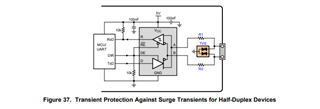
R1 is a CRCW0603010RJNEAHP with maximum power loss of 1/3W.
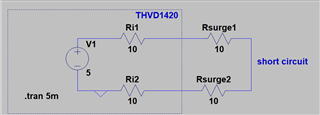
The short circuit output current of the THVD1420 is 250mA.
In case of a short circuit the losses in the two resistors is approx. 1.25W.
0.625W for each resistor.

So this resistors protect in case of a surge, but burn down during short circuit on the signal lines?
Right?

BR Wilfried

  • Yes, the surge protection protects only againsts surges.

    If you want all components to survive a short circuit, you have to design them for 250 mA.

  • Hi Wilfried,

    You are correct - if you want to protect the resistors against worst case short circuit current the power rating on the resistors need to be rated for the 250mA level. 

    Best,

    Parker Dodson

  • To save my reputation - as an engineer - I must now say:


    That was a trick question to the forum (it wasn't, of course).


    Figure 5-1 and Figure 5-2 are helpful.


    The driver output voltage decreases - resp. increases - by approx. 1.3V at 80mA output load.
    The two straight lines then meet at approx. 160mA (linear progression assumed).
    This would be the short circuit current.

    But this can be max. 250mA.

    This means that the output voltage decreases/increases by 2.5v when 250mA flow.


    This corresponds to an internal resistance of 10 Ohm in each driver line (in the chip).
    The surge resistors also have 10 Ohm. If the short circuit current is only 160mA the resistor value is 16 ohm.


    If the bus line is now short-circuited, 1.25V will drop at each internal resistor and at the surge resistors.
    1.25V*1.25V/10 Ohm = 0.156W

    Thus 1/3W is sufficient even in the case of a short circuit.

    Right?

  • Yes; you'd get 250 mA only without the resistors.

  • Hi Wilfried,

    So yes - the 250mA will only be reached without the resistors - and even then maybe not that high (its the max value). The 250mA max really is just saying that the part is RS-485 compliant. 

    However that being said - the linear approximation that you have made isn't exactly correct. The impedance on A/B is going to vary based on current and temperature since its a FET based driver. It does operate linearly - up to a point that is generally beyond normal operation (minimum differential resistance is 54 Ohms or 60 Ohms +/- 10%) - the picture shown shows a differential resistance of ~30 Ohms at room temperature (2.4V @ 80mA)  - this can vary though based on temperature  and can go either lower or higher depending on the temperature. 

    So long story short - its pretty likely you won't burn more than 1/3 W on the 10 Ohm resistor - but if the output / input impedance are lower do to application temperature then it could possible >1/3W.

    Please let me know if you have any other questions.

    Best,

    Parker Dodson