This thread has been locked.

If you have a related question, please click the "Ask a related question" button in the top right corner. The newly created question will be automatically linked to this question.

DS90UB940-Q1: ub940 black screen issue

Part Number: DS90UB940-Q1

Hi experts,

We are using ub927 and ub940 for application as below:

Issue: 

ub940 lock status ok,but soc mipi receiver can not sync to valid mipi clock.

Test has been done:

1.We monitored the mipi clock with the oscilloscope and the result is as below:

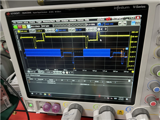
By comparing with the correct board, we discovered that the voltage amplitude of mipi clock of the failed chip is  829 mv,which is larger than the max value in mipi dphy specification(500 mv). The part number of the failed chip is dsub940n.

2. In our software start up sequence, first we set ub940 test pattern with internal clock and then close test pattern and switch to normal mode. We close the test pattern and let the chip work directly in normal mode and the black screen can not be displayed. 

Could you please explain in details that why closing test pattern can avoid black screen issue?

3. We did fota update of the whole system and when the system restarts from fota update, the i2c communication between the host machine and ub940 can not work. When we apply the oscilloprobe to measure the i2c waveform, the communication recovers. Could you please explain why?

Thanks in advance! 

  • Hi Wendy,

    2. For the software start up sequence, could you clarify what you mean by closing the test pattern and switching to normal mode? Is there a script you are using I could look at? It sounds like there is a configuration setup during test pattern that is needed for normal mode.

    3. What is done during the fota update? Is the host machine communicating via I2C passthrough on the UB927 or directly connected to the I2C port on the UB940?

    Regards,

    Jack

  • Hi Jack,

    Thanks for the prompt reply.

    2. For the software start up sequence, could you clarify what you mean by closing the test pattern and switching to normal mode? Is there a script you are using I could look at? It sounds like there is a configuration setup during test pattern that is needed for normal mode.

    For the register script with test pattern, I list it as follows:

    regaddr=0x64, data=0x0
    regaddr=0x66, data=0x3
    regaddr=0x67, data=0x3
    regaddr=0x66, data=0x7
    regaddr=0x67, data=0x0
    regaddr=0x66, data=0x8
    regaddr=0x67, data=0x5
    regaddr=0x66, data=0x9
    regaddr=0x67, data=0x2d
    regaddr=0x66, data=0x4
    regaddr=0x67, data=0x72
    regaddr=0x66, data=0x5
    regaddr=0x67, data=0xe6
    regaddr=0x66, data=0x6
    regaddr=0x67, data=0x2e
    regaddr=0x66, data=0xc
    regaddr=0x67, data=0xdc
    regaddr=0x66, data=0xd
    regaddr=0x67, data=0x14
    regaddr=0x66, data=0xa
    regaddr=0x67, data=0x28
    regaddr=0x67, data=0x5
    regaddr=0x65, data=0x5
    regaddr=0x64, data=0xb1
    regaddr=0x1, data=0x2
    regaddr=0x6c, data=0x13
    regaddr=0x6d, data=0x80
    regaddr=0x6c, data=0x14
    regaddr=0x6d, data=0x80
    regaddr=0x6b, data=0x50
    regaddr=0x6c, data=0x13
    regaddr=0x6d, data=0x80
    regaddr=0x6c, data=0x13
    regaddr=0x6d, data=0xbf
    regaddr=0x6c, data=0x14
    regaddr=0x6d, data=0x80
    regaddr=0x6c, data=0x14
    regaddr=0x6d, data=0xbf

    First, the test pattern is applied  Then a digital soft reset is applied to close the test pattern mode.

    The configuration with no test pattern is listed as follows:

    regaddr=0x1, data=0x2
    regaddr=0x6c, data=0x13
    regaddr=0x6d, data=0x80
    regaddr=0x6c, data=0x14
    regaddr=0x6d, data=0x80
    regaddr=0x6b, data=0x50
    regaddr=0x6c, data=0x13
    regaddr=0x6d, data=0x80
    regaddr=0x6c, data=0x13
    regaddr=0x6d, data=0xbf
    regaddr=0x6c, data=0x14
    regaddr=0x6d, data=0x80
    regaddr=0x6c, data=0x14
    regaddr=0x6d, data=0xbf

    For normal mode the test pattern is not needed. It is applied for debug purpose only.

    3. What is done during the fota update? Is the host machine communicating via I2C passthrough on the UB927 or directly connected to the I2C port on the UB940?

    the fota update updates the software package of the host machine with ub940 on it. During the update the ub940 is not operated but after the fota update a soft reset is applied to the host machine without power supply cutting down. Durning the system start up we discovered the i2c communication failure. The host machine is directly connected to the i2c port on the ub940.

    Regards,

    Wendy

  • Hi Wendy,

    2. Have you tried using patgen on the 927? This would give us a better indication of the system's status since the video has to go across the link. 

    3. The soft reset is most likely the cause of the i2c communication failure. Can you try power cycling the ub940 to see if that restores i2c communication after fota update?

    Would you also be able to provide register dumps for the ub927 and the ub940?

    Regards,

    Jack

  • 2. Have you tried using patgen on the 927? This would give us a better indication of the system's status since the video has to go across the link. 

    ub927 is not on the host machine,we know nothing about the machine with ub927 carried on. It is owned by another company. We don't know its iic address. Is it possible to use other method to solve this problem?

    3. The soft reset is most likely the cause of the i2c communication failure. Can you try power cycling the ub940 to see if that restores i2c communication after fota update?

    The ub940 pwd is directly connected to VCC and it can not be toggled down. Is there any other way to solve this probem?

    Best Regards

    Wendy

  • Hi Wendy,

    2. Do you know the video timing/resolution coming from the UB927? There are certain supported video resolutions for the UB940. If the display cannot sync to the video signal, it will not display any image. I will attach an app note about configuring UB940 timing parameters for your reference.

    App Note: Link

    3. There is some errata related to digital resets that should be implemented if not already.

    • Before a DIGITAL RESET1 or DIGITAL RESET0, set the CSI indirect address (CSIIA) register to point to an unused register location (0x6C=0xFF)
    • After issuing a DIGITAL RESET1 or DIGITAL RESET0, wait >=500us before accessing any registers via I2C

    Regards,

    Jack