This thread has been locked.

If you have a related question, please click the "Ask a related question" button in the top right corner. The newly created question will be automatically linked to this question.

DS125DF410: VCO locking range and VCO Cap DAC/LPF DAC VAL settings

Part Number: DS125DF410

Hi TI Team,

We have a few questions relating to the locking function of DS125DF410.

  1. What is the guaranteed VCO locking range of DS125DF410? Is it 9.8GHz ~ 12.5GHz?
  2. What's the relationship between Reg 0x08 (Starting VCO cap dac setting 0) and Reg 0x0B (Starting VCO cap dac setting 1)? How about Reg 0x1F (lpf_dac_val override)? How do they interact during the locking process?
  3. How can we instruct the CDR to lock based on a set of fixed settings (ONLY, as we know exactly what the incoming signal's data rate is) with Reg 0x08, 0x0B and 0x1F?

Thanks.

Child

  • Hi Child,

    1) Yes, the VCO will lock to data between 9.8-12.5 Gbps (and subrates).

    I can look into question 2/3 in order to provide a more in depth answer.  With that said, can you help me understand why you're interested in using these?  Typically the use of registers 0x60-0x64 and 0x2F are sufficient for acquiring CDR lock to a given datarate.

    Thanks,
    Drew

  • Hi Child,

    The starting VCO cap dac settings essentially determine the frequency at which the VCO starts during the lock process.  The LPF dac adjusts the LPF in the PLL.

    What issue are you running into with the retimer?

    Thanks,
    Drew

  • Drew,

    We were trying to do a system loop-back test (PRBS at TX @6.25Gbps --> CDR at RX with PROP3). We noticed that some of the RX channels would go unlocked after resetting their CDRs. The issues did not happen every single time after the CDRs were reset. So, we were thinking of limiting CDR's search range to fix the issues - because we know exactly what the TX is outputting. Can that be done?

    In addition, you mentioned Reg 0x60~0x64 (GRP0/1 OV CNT, GRP0/1 OV DLTA). Can you tell us more about the use of them? Or, can you point us to the literature with more explanation?

    Thanks.

    Child

  • Hi Child,

    Please allow me to check with a colleague on some of these details.  I will provide an update tomorrow on this.

    Can you clarify if you are using REF_MODE 1 or 3?

    Thanks,
    Drew

  • It's REF_MODE 3 on both the Tx and Rx.

  • Hi Child,

    In addition, you mentioned Reg 0x60~0x64 (GRP0/1 OV CNT, GRP0/1 OV DLTA). Can you tell us more about the use of them? Or, can you point us to the literature with more explanation?

    I don't have any super detailed documentation on these.  In general, setting these determines the data rate that the CDR block in the device will lock to, but does not impact the VCO cap dac settings.  Please see section 7.3.5 and 7.4.4 in the datasheet for some additional details on this.

    So, we were thinking of limiting CDR's search range to fix the issues - because we know exactly what the TX is outputting. Can that be done?

    I will look into this.  You mention that some of the RX channels unlock after resetting CDR.  Do you mean that they unlock during normal operation, or just during CDR reset?

    Thanks,
    Drew

  • Drew,

    Thanks for the additional info about Reg 0x60~64. I will go back to the datasheet sections for more details.

    I may have given you inaccurate info about the the unlocking issue. We noticed the intermittent unlocking issue after running the eye-capturing sequence, not after resetting the CDR (sorry about that). Sometimes, the CDR goes unlocked (and stays unlocked) after running the sequence but may be recovered by running it again.

    ====================

    # Eye-capturing sequence

    ====================

    page(ch)
    wrm(0x11, 0xe0, 0xe0) # set eye voltage range & set EOM_PD
    wrm(0x11, 0xc0, 0xe0) # set eye voltage range & unset EOM_PD
    wrm(0x3e, 0x00, 0x80) # disable lock monitoring function
    wrm(0x11, (int(lvl / 100 - 1) << 6) | 0x00, 0xe0) # set eye voltage range & unset EOM_PD
    wrm(0x2c, 0x00, 0x40) # set VEO_SCALE to 0
    wrm(0x23, 0x80, 0x80) # set EOM_GET_HEO_VEO_OV to 1
    wrm(0x24, 0x80, 0x80) # enable fast EOM
    wrm(0x24, 0x02, 0x02) # set EOM_GET_HEO_VEO to 1
    wrm(0x24, 0x01, 0x01) # EOM_START
    rd_2bytes(0x25) # read and discard the first 4 bytes of data
    rd_2bytes(0x25)
    for j in range(0,64):
    for i in range(0,64):
    vals = rd_2bytes(0x25)
    ber[i,j] = vals[1] + vals[0] * 256
    wrm(0x2c, 0x40, 0x40) # set VEO_SCALE to 1
    wrm(0x3e, 0x80, 0x80) # enable lock monitoring function
    wrm(0x11, 0x20, 0x20) # set EOM_PD
    wrm(0x24, 0x00, 0x80) # disable fast EOM
    wrm(0x23, 0x80, 0x80) # set EOM_GET_HEO_VEO_OV to 1
    wrm(0x24, 0x02, 0x02) # set EOM_GET_HEO_VEO to 1

    # Note:
    # page() changes the register page per value of ch
    # wrm(reg, val, mask) writes the register with the val and mask provided

    Do you see any issue with the sequence that causes the CDR to unlock after running it?

    Thanks.

    Child

  • Hi Child,

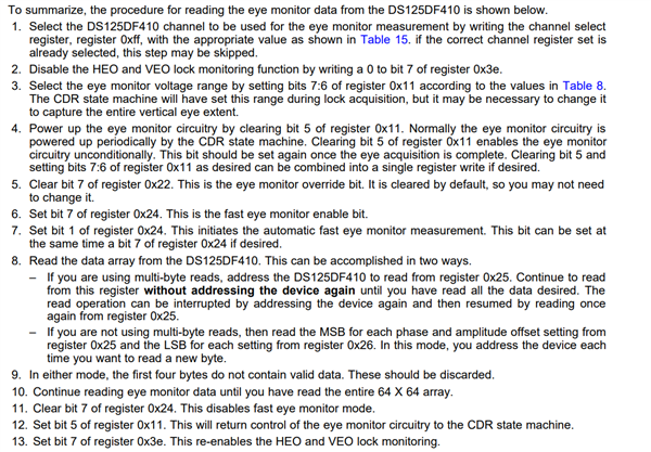
    I don't see anything that appears obviously wrong with the procedure you have.  However, I did notice that it deviates a bit from the procedure in the datasheet.  I believe I have modified your code to closely follow the procedure from the datasheet.  Could you test the procedure below to see if there is any change in behavior?

    One difference that I did note between your code and the datasheet was the order between disabling heo/veo lock monitoring function and powering on the eye monitor circuitry.  Not sure if this would have any real world impact though.

    page(ch)
    wrm(0x3E, 0x00, 0x80) # Disable lock monitor function
    wrm(0x11, (int(lvl / 100 - 1) << 6) | 0x00, 0xe0) # set eye voltage range & unset EOM_PD
    wrm(0x22, 0x00, 0x80) # Might be unnecessary, just following datasheet
    wrm(0x24, 0x80, 0x80) # Enable fast eom
    wrm(0x24, 0x01, 0x01) # Start EOM
    rd_2bytes(0x25) # read and discard the first 4 bytes of data
    rd_2bytes(0x25)
    for j in range(0,64):
        for i in range(0,64):
            vals = rd_2bytes(0x25)
            ber[i,j] = vals[1] + vals[0] * 256
    wrm(0x24, 0x00, 0x80) # Disable fast EOM
    wrm(0x11, 0x20, 0x20) # Set EOM_PD
    wrm(0x3E, 0x80, 0x80) # Enable lock monitor function
    Thanks,
    Drew
  • Drew,

    Your sequence seems to be more stable. But it does not let us set the Vrange manually. Instead, Vrange's are set automatically. What should be changed to make Vrange manually adjustable?

    Thanks.

    Child

  • Hi Child,

    Glad to hear this is a more stable sequence.

    Vrange override can be accomplished by clearing bit 6 of register 0x2C.  I would clear it after configuring register 0x11.  Updated sequence below.

    page(ch)
    wrm(0x3E0x000x80# Disable lock monitor function
    wrm(0x11, (int(lvl / 100 - 1) << 6) | 0x000xe0# set eye voltage range & unset EOM_PD
    wrm(0x2C, 0x00, 0x40) # Override Vrange
    wrm(0x220x000x80# Might be unnecessary, just following datasheet
    wrm(0x240x800x80# Enable fast eom
    wrm(0x240x010x01# Start EOM
    rd_2bytes(0x25# read and discard the first 4 bytes of data
    rd_2bytes(0x25)
    for j in range(0,64):
        for i in range(0,64):
            vals = rd_2bytes(0x25)
            ber[i,j] = vals[1] + vals[0] * 256
    wrm(0x240x000x80# Disable fast EOM
    wrm(0x2C, 0x40, 0x40) # Disable Vrange override
    wrm(0x110x200x20# Set EOM_PD
    wrm(0x3E0x800x80# Enable lock monitor function

    Thanks,

    Drew

  • Drew, that works quite well. Thanks!