Part Number: DP83822I
Hi,
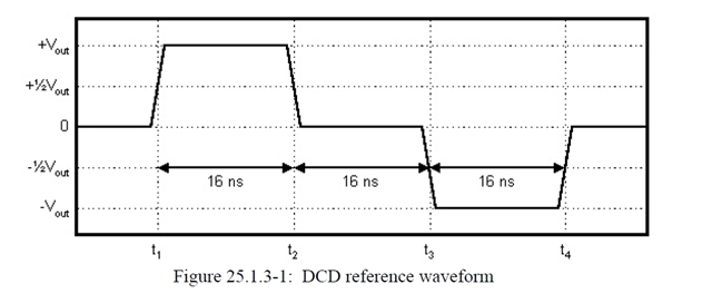
For the 100BASE-TX Duty Cycle Distortion Test (DCD) there is a "01010101 NRZ" pattern needed.
How can I generate this pattern with the DP83822I PHY?
Thanks and best regards,
Patrick
Part Number: DP83822I
Hi,
For the 100BASE-TX Duty Cycle Distortion Test (DCD) there is a "01010101 NRZ" pattern needed.
How can I generate this pattern with the DP83822I PHY?
Thanks and best regards,
Patrick