Hello TI members,
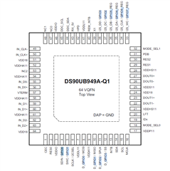
I am facing some issues related to I2S output from the Serializer device, right now I am using DS-949 based EVK kit. I want to feed the HDMI input to the Serializer and want to get the HDMI audio out from the Serializer through the below pins. MODE_0 = #1, MODE_1 = #1
I have a 2-channel input (Stereo input), so just want the I2S_DA of the Serializer to give me HDMI audio output. After searching through the TI forums, I found that by default, without setting any registers of the Serializer, I can get the I2S audio output from I2S_DA after setting 0x55[6] = 1, and yes, I am getting output from I2S_DA.
I have a few questions to ask about the above I2S things.
1. How can I set the I2C_CLK of the Serializer which is coming out from the Serializer device and how I2S_CLK is set to give a particular frequency?
2. If I set MODE_1 = #5, i.e., External Bridge Control, then can I get the I2S output from the Serializer or not?
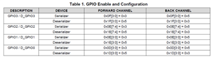
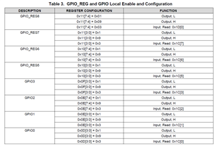
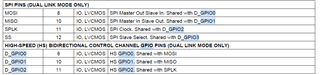
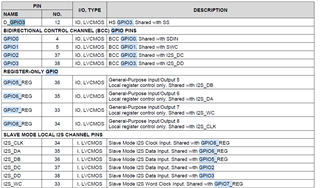
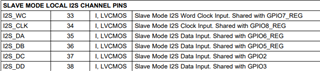
3. In the above, I just want the 2-channel output from the Serializer, so just using I2S_DA for the Serializer, rest the I2S_DB, and I2S_DC pins of I2S, I want to use them as a normal GPIO mode, as, mentioned below in datasheet
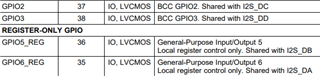
as these pins are shared by I2S pins, so when I am configuring them as GPIO output pins using 0x0E, 0x0F, and 0x10 register, I am not able to control the GPIO pins of I2S_DB, I2S_DC, and I2S_DD. Please share me how can I use them as normal GPIO output pins.
Thank you.
Regards,
Vivek Karna