Part Number: P82B96
Dear suport team.
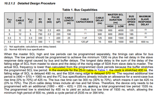
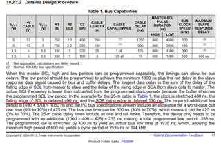
I am trying to understand the explanation of "10.2.1.2 Detailed Design Procedure" in the datasheet while calculating with the help of the annotations of figures 7-figure 9.
However, I cannot understand the formulas written in the annotations of figure 7 to 9. Please help me.
First, about the formula of figure 7 "Effective Delay of SCL at Slave"
What does the first term 255 represent? I looked in the datasheet, but the constant 255 only appears here.
What does the constant 17 in 17VCCM mean?
What does the constant 2.5 in parentheses mean? Its mean the RX/RY input capacitance of 2.5pF (typ)? If so, why isn't 2.5 multiplied by 10^-12?
Why multiplying Cb by 4x10^9? What does 4x10^-9 mean?
Next, about the formula of figure8 "Effective delay of SCL at master"
What does 0.7 in 0.7RbCb mean? It seems that the value is different from the input "High" threshold (0.58xVCC).
Finally, about the formula "Effective delay of SDA at master" in figure 9
What does 0.2 in 0.2RsCs mean?
Thank you and regards,