This thread has been locked.

If you have a related question, please click the "Ask a related question" button in the top right corner. The newly created question will be automatically linked to this question.

DS100BR111A: EQA1 EQB1

Part Number: DS100BR111A
Other Parts Discussed in Thread: DS100BR111

Hi Team,

For DS100BR111A,

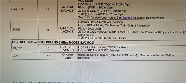
In pin mode, must the pull-up and pull-down states of EQA1 and EQB1 be the same?

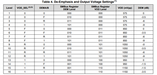
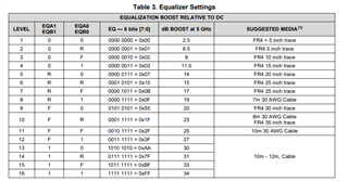
In addition, when debugging EQ and DEM, what is the recommended direction? Which one to call first?

Do the answers to the above two questions also apply to DS100BR111? Thanks.

Regards, Charlie

  • Hi Charlie,

    1). Pull up or down may not be the same. This depends on the CTLE gain or level that you are planning to use.

    2). Suggestion is to set both EQ and DEM at the lowest level. Then increase EQ level first - one step at a time - until there is a valid eye opening. It is preferred to set DEM at the lowest or no de-emphasis and let EQ compensate for the data dependent jitter. After sweeping EQ levels, if sweeping through all EQ level did not provide acceptable eye opening - then one can set the EQ level at the lowest level with the DEM at a step higher then sweep the EQ level again. This can continue until optimum eye opening is achieved.

    Regards,Nasser

  • Hi Nasser,

    Thanks for your support. My customer encountered some debugging problems, I have sent to your mailbox. Please deal with it as soon as possible, the project is very important. Thanks.

    Regards, Charlie

  • Hi Charlie,

    Customer had sent us schematic through email. Please let's use E2E so we can track and allow other customers to use this knowledge as well.

    Schematic shows pin 6 floating. Please pull this pin low through a 1K-ohm Resistor. Please note customer schematic shows this part as DS110BR111 - correct part number is DS100BR111.

    Regards,Nasser

  • Hi Nasser,

    Thanks for your update.

    The schematic diagram I emailed to you because the customer's schematic diagram is not convenient to display on e2e.

    The customer's pin 6 forgot to pull down, can this be configured through the I2C interface? Thanks.

    Regards, Charlie

  • Hi Charlie,

    If customer is using SMBus slave mode, then TX_DIS can be configured through register 0x04. Set bit 5 to 1 to enable TX_DIS override and bits 4 and 3 to 0 to enable both channels A and B.

    Best,

    Lucas

  • Hi Lucas,

    My customer has configured 0x04=0x20. OUTB still has no signal, But OUTA has signal.

    R&D have confirmed that registers can be read and written via SMBus. And pin3 has been set high.

    But When 4 is set to 1, OUTA still has signal.

    Now the feeling is that the registers can be read and written, but out A and OUT B cannot be enabled or disabled.

    What is the reason for this? What is the order of register configuration? Thanks.

    Our goal is to enable both A and B to output  signal.

    Regards, Charlie

  • Hi Nasser,

    Can you help with the case: SMBus can read and write successfully, but OUTA and OUTB cannot be enabled or disabled? Thanks.

    Regards, Charlie

  • Hi Charlie,

    Can the customer check the following?

    • Is ENSMB pin pulled high with 1k resistor?
    • Is READEN pin tied low?
    • Is the correct slave address set with AD[3:0] pins being used?
    • Try setting reg 0x06 bit 3 to 1

    Best,

    Lucas

  • Hi Lucas,

    Thanks for your support.

    All the above conditions have been met.

    Registers can already be read and written via SMBus. However, it is not possible to choose whether the output is capable or not.

    Have you encountered this situation before? Thanks.

    Regards, Charlie

  • Hi Charlie,

    Can you confirm customer is setting Reg 0x06[3] before accessing any register?

    Best,

    Lucas

  • Hi Lucas,

    Finally, my customer changed the EQ value to a smaller value, and the problem was solved. Thanks.

    Regards, Charlie