This thread has been locked.

If you have a related question, please click the "Ask a related question" button in the top right corner. The newly created question will be automatically linked to this question.

TCAN4550: TCAN4550: Can't receive SDO data from TCAN4550

Part Number: TCAN4550

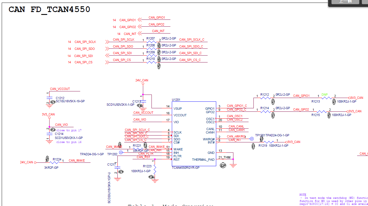
We are integrating the TCAN4550 into our system. 

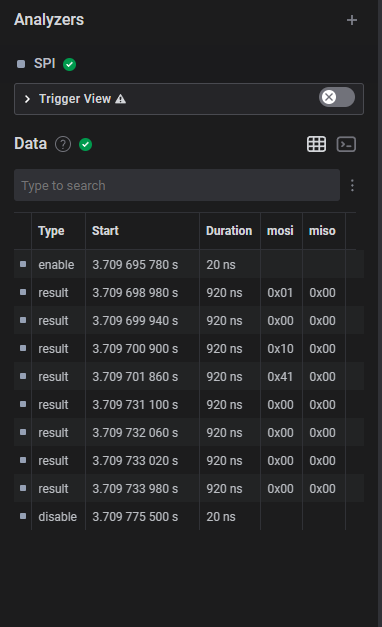
Initialize the SPI directly after powered on, and then perform the read operation.

The SPI communications is working. But SDO can't receive any data like below chart:


DTS config:

&spi2 {
     status = "okay";
     max-freq = <50000000>;
     cs-gpios = <&gpio2 RK_PB4 GPIO_ACTIVE_LOW>;
     tcan4x5x: tcan4x5x@0 {
           compatible = "ti,tcan4x5x";
           reg = <0>;
           #address-cells = <1>;
           #size-cells = <1>;
           spi-max-frequency = <10000000>;
           clock-names = "cclk", "hclk";
           clocks = <&tcan4x5x_cclk>, <&tcan4x5x_hclk>;
           bosch,mram-cfg = <0x0 2 1 4 5 0 3 10>;
           pinctrl-names = "default";
           pinctrl-0 = <&pwr_en>, <&data_ready>;
           pwr_en-gpios = <&gpio2 RK_PA2 GPIO_ACTIVE_HIGH>; /* GPIO2_A2 */
           data-ready-gpios = <&gpio2 RK_PB0 GPIO_ACTIVE_LOW>; /* GPIO2_B0 */
           status = "okay";
       };
};

&pinctrl {
       tcan4x5x {
            pwr_en: pwr-en {
                  rockchip,pins = <2 RK_PA2 RK_FUNC_GPIO &pcfg_pull_up>;
            };
            data_ready: data-ready {
                  rockchip,pins = <2 RK_PB0 RK_FUNC_GPIO &pcfg_pull_up>;
            };
       };

 };

  • Nick,

    An engineer has been notified of this post and will respond by end of business 11/3/2022 CST.

    Regards,

    Eric Hackett

  • Hello Nick,

    It looks like your SPI byte sequence is inverted within the two 32-bit words.  The "0x41" byte should be the first byte transmitted following the chip select (enable) pin transitioning low for a SPI Read transaction. 

    It looks to me from your analyzer plot that the byte sequence transmitted is:

    0x01, 0x00, 0x10, 0x41, 0x00, 0x00, 0x00, 0x00

    If I invert the bytes in the two words, I would get:

    0x41, 0x10 0x00, 0x01, 0x00, 0x00, 0x00

    This looks to me like you are trying to read register 0x1000 (the Core Release Register).  Is this correct?

    If so, the correct byte sequence to be transmitted for single register SPI read of register 0x1000 is:

    0x41, 0x10 0x00, 0x01, 0x00, 0x00, 0x00

    Try adjusting your SPI driver to transmit MSB first.  Hopefully this resolves the issue.

    Regards,

    Jonathan

  • Hi Jonathan,

    We adjusted SPI driver to transmit MSB first, but MISO still get 0xff

    And I have another question, is that necessary need to control the RST pin?

  • Hi Nick,

    The RST pin must be Low for normal operation.  The TCAN4550 will be held in Reset (power on reset) when the RST pin is High.

    I see the thread state has been changed to Closed.  Have you resolved your issues and got it working?

    Regards,

    Jonathan

  • Hi Jonathan,

    We don't resolve our issue yet.

    I will try to check the status of RST pin in next week.

    Thanks.

    Nick

  • Hi Nick,

    Ok.  In addition to checking the RST to make sure it is low, can you also verify the VIO pin has the correct voltage on it and that there is a valid clock on the OSC1/2 pins?

    I noticed in the schematic that there was 2 different net names for the net connected to the VIO pin.  The layout tool will have to pick one of the net names to use, but I wanted to make sure that it still got connected on the board to the 3V3 supply.  VIO is needed for the SPI and clock circuitry to function.

    The digital core also needs a clock in order to write and read the register values, so just verify you see an oscillating clock on the OSC1/2 pins.  If the clock is not functioning, the SPI won't return a value for most of the registers.  The registers 0x0000 to 0x0010 are implemented in logic and do not require the OSC1/2 clock to be functional and only requires the SPI clock to return a value.  You can also try reading the Device ID registers 0x0000 and 0x0004 to help detect a possible clocking issue.

    Regards,

    Jonathan

  • Hi Nick,

    Has this issue been resolved and can we close this thread?

    Regards,

    Jonathan

  • Hi Jonathan,

    Yes, this issue been resolved.

    Thanks for your help.

    Nick.