


Part Number: DS90UB933-Q1
Other Parts Discussed in Thread: DS90UB934-Q1, , DS90UB947-Q1, DS90UB948-Q1, ALP
1. Why are we used to using coaxial transmission on the camera side, similar to DS90UB933-Q1 and DS90UB934-Q1 applications
By default, the drive display uses differential signal transmission similar to DS90UB947-Q1 and DS90UB948-Q1, DS90UB927-Q1 and DS90UB928-Q1 applications
-----What is the problem with driving the display screen with a single ended coaxial cable?
2. If you want to test DS90UB947-Q1 and DS90UB948-Q1 eye maps without modifying the software, what are the methods
----Is it possible to directly connect CMLOUTP and CMLOUTN with a 0.1uF capacitor, and add the test tool to both ends of the 0.1uF capacitor to test the eye diagram?
3. Why only supply power to the deserializer (no signal)? RIN0 -, RIN0+will have waveforms as follows:
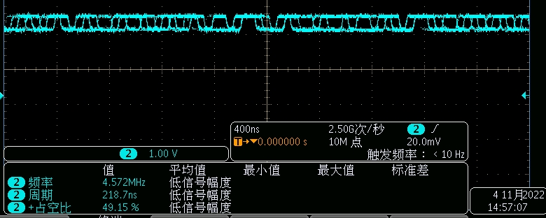
4. How the above waveform is generated.
