This thread has been locked.

If you have a related question, please click the "Ask a related question" button in the top right corner. The newly created question will be automatically linked to this question.

DS90UB914A-Q1: 914 cannot access 933's address

Part Number: DS90UB914A-Q1

Hi,

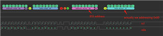
We met a IIC communication problem between 933 and 914. The signal flow is SOC->914->connectors & coax cable->933->ISP->image sensor. Clock signal flow is OSC(42Mhz)->933->ISP(84Mhz PCLK output)->933-> connectors & coax cable->934. But we found that 933 can transfer the image signal flow to 914 but 914 cannot access 933 and other slave devices on camera side. The camera with 933 is normal because it can be accessed by 934. But the 914 device now is abnormal because it cannot communicate with 913 and 914 devices. We captured the local IIC data from the 914 side and found there is NACK when addressing 913(the 7bit IIC address is 5A). And the next operation(write register address) was incorrect, It seems that the data is shifted 1 bit to the left, and then both the SDA and SCL levels become HIGH. You can see the details from the following screenshots:

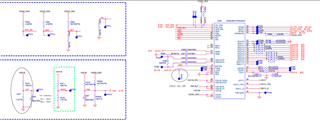
The hardware design is shown in the following figure:

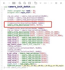
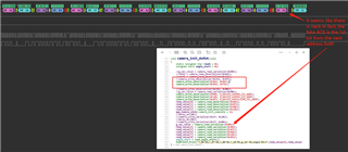
We tried not to configure any of the 933's registers, forward channel communication is actually normal, but once we start accessing 933 and try to access the registers (read/write), the LOCK signal will be pulled LOW, I don't know what causing this problem and hope some suggestions from you, thanks!

  • Hello Rogers,

    I will look into this and come back to you with a reply.

  • Hello Rogers,

    I am not sure I understood the problem correctly! Hence, please correct me if I am wrong:

    You have 2 ECU boards, one board with the UB934 on it and the second ECU has the 914A on it.

    If you pair the UB934 with the Camera, you can access the Camera, i.e. UB933 and ISP via Back channel. But if you pair the UB914A with the Camera, you cannot access the UB933 and ISP via Back channel. Correct? And if you start accessing the UB933 via Back channel the LOCK signal will be pulled LOW. correct?

    What is the difference between the used MODE on both boards, with UB914A and with UB934?

  • Hi Hamzeh,

    In fact, the board is 914 and 934 compatible (different pin definitions between 914 and 934 are considered in the hardware design). Yes, your description is exactly correct, if the MCU does not access the 933 through the 914, the image data can be transmitted to the 914 side through FC, and the GPIO0/1 signals can also be transmitted to the 933 through the BCC. Once the 933 and its  registers are accessed via I2C, the LOCK signal on the 914 side is pulled low.

  • Hi Rogers,

    I am trying to find any relation between I2C access and LOCK status, but I can't!! Indeed, there is no relation, and I can't think of any!

    Can you provide the schematics for both boards, i.e. 914A and 934. Also, the 933 schematic would be good to have. You can send these to my email: h-jaradat(at)ti(dot)com.