This thread has been locked.

If you have a related question, please click the "Ask a related question" button in the top right corner. The newly created question will be automatically linked to this question.

TLIN1021A-Q1: Device does not come out of 'standby mode / 'sleep mode', Datasheet is unclear on what states pins should be in for this device to work properly.

Part Number: TLIN1021A-Q1

Hi, 

I am seeing an intermittent issue with this chip, the state-machine functionality seems to be poorly implemented and leads to undefined behaviour. 

We are trying to deploy this on a product and it is being made very difficult by the intermittent operation of this chip. 

The datasheet does not state, a basic set up of all pins to enable normal operation - the WAKE pin and WAKE functionality is impeding this chip from working and it seems to be operating in some undefined state and will NOT come out of Standby / Sleep mode despite all of our efforts. 

Please update the datasheet and associated information for this chip to clearly define what pins states should be when their functionality is not used, for instance WAKE can be tied either HIGH or LOW to VSUP, as per information in on this forum - this information is however missing from the datasheet, which is poor as instructions go. 

As per datasheet and information on these forums, I have made modifications to my PCBs that ties INH to GND through a 100k resistor, we were toggling the EN pin using a GPIO of a MSP430 associated processor, however I believe this was leading to timing issues as stated in the datasheet and the state-machine description, the EN pin should be enabled at start up, so I have cut the track and pulled it HIGH through a resistor to 3.3V, please advise whether this is still suitable, or whether it should be pulled directly to 3.3V, without a resistor. 

We are sending an 11-bit low wake up request on start up, but the TLIN1021 does not come out of this indeterminate mode. I have measured the behaviour and Tx is being pulled HIGH, Rx is sitting LOW. We are currently experimenting with toggling our dominant LIN bus, to see if we can initiate a wake-up request, which by all other means seems to be ignored. 

Pull-ups are enabled on MSP430 on the open drain Rx line, please advise if this is not acceptable, however we have 5/10 boards that work perfectly, and 5/10 boards that have this strange, intermittent, undefined state-behaviour, which I am currently convinced is a function of the overly complicated control system and state-machine that has been implemented into this device. 

Please advise on how we can trouble-shoot this problem 

  • Hi Harry,

    The datasheet does not state, a basic set up of all pins to enable normal operation - the WAKE pin and WAKE functionality is impeding this chip from working and it seems to be operating in some undefined state and will NOT come out of Standby / Sleep mode despite all of our efforts. 

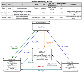
    We show this on table 9-1 Operating Modes:

    What you'll notice is that the only pin that determines whether this device is in normal mode or not is the EN pin. The TXD pin determines if the bus is reccesive or dominant. RXD and INH are output pins. The WAKE pin does not determine if you go into normal mode or not. What it can do is create a wake request that automatically transitions you out of sleep mode into standby mode. But it will not stop you from going into normal mode.

    Please update the datasheet and associated information for this chip to clearly define what pins states should be when their functionality is not used, for instance WAKE can be tied either HIGH or LOW to VSUP, as per information in on this forum - this information is however missing from the datasheet, which is poor as instructions go. 

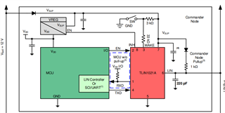
    Sorry that the datasheet is confusing, this is a rather complicated device when it comes to transceivers. We have multiple diagrams throughout the datasheet that show how you can connect the WAKE pin including one in the typical application section:

    If the WAKE pin is unused it can be tied to VSUP or GND. You don't need any kind of resistor. This will just remove the LWU functionality from the device.

    As per datasheet and information on these forums, I have made modifications to my PCBs that ties INH to GND through a 100k resistor, we were toggling the EN pin using a GPIO of a MSP430 associated processor, however I believe this was leading to timing issues as stated in the datasheet and the state-machine description, the EN pin should be enabled at start up, so I have cut the track and pulled it HIGH through a resistor to 3.3V, please advise whether this is still suitable, or whether it should be pulled directly to 3.3V, without a resistor. 

    You can just leave the INH pin floating. This is an output pin and does not need to be tied to any logic level. What timing issues were you running into? The EN pin can be pulled high externally from the device to keep it in normal mode. But you should still have some connection to the MCU if you wish to toggle between normal and sleep mode. 

    The datasheet does not state, a basic set up of all pins to enable normal operation - the WAKE pin and WAKE functionality is impeding this chip from working and it seems to be operating in some undefined state and will NOT come out of Standby / Sleep mode despite all of our efforts

    If your device is in standby or sleep mode and your EN pin is pulled high then you most likely have an undevoltage event. Can you provide a scope shot of your EN, TXD, VSUP, and INH pin?

    Also do you have any schematics that you can provide? I would be happy to do a schematic review for you.

    We are sending an 11-bit low wake up request on start up, but the TLIN1021 does not come out of this indeterminate mode. I have measured the behaviour and Tx is being pulled HIGH, Rx is sitting LOW. We are currently experimenting with toggling our dominant LIN bus, to see if we can initiate a wake-up request, which by all other means seems to be ignored. 

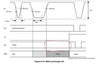
    The LIN transceiver will not automatically transition out of standby mode after a wake request. What happens is the device will report this wake request on the RXD pin by pulling it low:

    It is not up to the transceiver to drive the EN pin high that is actually the job of the MCU to transition the device to normal mode by driving the EN pin high.

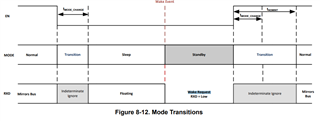
    We document how our device transitions in our state diagram below:

    What you'll notice is that everything is controlled by the EN pin and there are other fault cases that can transition the device into other modes.

    We are sending an 11-bit low wake up request on start up, but the TLIN1021 does not come out of this indeterminate mode. I have measured the behaviour and Tx is being pulled HIGH, Rx is sitting LOW.

    It sounds like you are receiving the wake request on the RXD pin since it is sitting low after you send the 11-bit low wake up. Now you have to have your MCU read this low and drive the EN pin high.

    Pull-ups are enabled on MSP430 on the open drain Rx line, please advise if this is not acceptable, however we have 5/10 boards that work perfectly, and 5/10 boards that have this strange, intermittent, undefined state-behaviour, which I am currently convinced is a function of the overly complicated control system and state-machine that has been implemented into this device. 

    A pull up is required on RXD so that is good that you have them enabled. 

    It would be good if we could get some scope shots. On the board that is not working, turn it on and probe VUSP, EN, TXD, and INH. Then drive signal on the TXD pin and probe TXD, LIN, RXD, and VSUP. Make sure you do not trigger the dominant time out on the TXD pin. That will turn the driver off.  If you can provide any schematics that would be very helpful in debugging this issue.

    Best,

    Chris

  • Harry,

    Chris's response is correct. Ultimately, I worry there might have been some confusion between the functions of the different pins. Keep in mind that the EN effectively turns the device on and off (specifically brings the device into and out of Normal mode).

    Communication is only possible in Normal mode. If EN = high and power is supplied, you will be in Normal mode, capable of communication, unless an undervoltage or thermal shutdown condition exists.

    WAKE events can occur in multiple forms. They could be wake-up frames (WUF), as you described below as a long dominant signal. They could also be local wake-up (LWU) events, which are simply high-low or low-high transitions on the WAKE pin (battery level, not VCC).

    EN = high will bring you to Normal mode whether you were in Sleep or Standby. Powering on with EN = high will bring you to Normal mode.

    I will copy the format of Table 6-1 in the data sheet to help elucidate the pin behaviors.

    Name # Type I/O
    RXD 1 Logic Output
    EN 2 Logic Input
    WAKE 3 HV edge-triggered Input
    TXD 4 Logic Input*
    GND 5 Reference Input
    LIN 6 HV Bus I/O
    VSUP 7 Supply Input
    INH 8 HV Logic Output

    *TXD can also behave as an output to indicate the wake source in Standby mode.

    Best,

    Danny