This thread has been locked.

If you have a related question, please click the "Ask a related question" button in the top right corner. The newly created question will be automatically linked to this question.

DS90UB960-Q1: Using DS90UB960-Q1 with DS90UB953-Q1(Camera). After Camera Power-Off & On , We get Failure MIPI-CSI data .

Part Number: DS90UB960-Q1
Other Parts Discussed in Thread: DS90UB953-Q1

Dear TI expert,

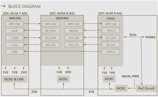
We are using DS90UB960-Q1 and DS90UB953-Q1.Our sysytem is in below.

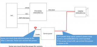
Some cars must drop the power for camera.

Then Camera and DS90UB953-Q1 aren't worked.DSDS90UB960-Q1 contines to be worked.

After 2,3seconds, recover the power for camera, but The video data in Soc is no data.

Maybe SoC can't get video data from DS90UB960-Q1.

Camera Vendor said, the power of camera needs to down to 0V once, and power on again.

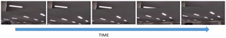
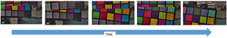
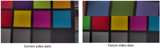
So we did it, the video data came back in SoC , but capture image is incorrect. ( Please refer Failure video data in below)

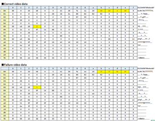
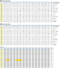
I'd checked the DS90UB960-Q1 register,   results in below.

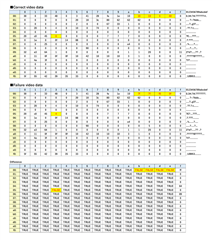
I'd checked the DS90UB953-Q1 register,   results in below.

Could you please tell us how to recover in DS90UB960-Q1  from the phenomenon?

Best regards.

  • Hi, 

    Thanks for your question. Since Nov. 24 & Nov. 25th are US holidays, the team will resume activity on E2E upon return on Monday Nov. 28th. Thanks for your patience. 

    Regards, 

    Logan

  • Hi, Logan.

    Thanks to reply.

    Sure. We look forward to your answer.

    Best regards.

  • Hello,

    Thank you for your patience during the holiday. Does the failure video data remain in the failed state permanently or only for a few frames? Does the video data ever recover on its own? If the 953 is powered down for 2 to 3 seconds then the device will return back to default register settings when it is repowered and any register configurations done prior will need to be repeated. If any of those configurations are necessary for the data to be received, that could explain the failure. Can you try to rerun the 953 initialization script or rewrite the necessary registers after the device is repowered?

  • Hi, Darrah

    Thank you for your reply.

    Does the failure video data remain in the failed state permanently or only for a few frames? 

    ⇒It appears randomly, but most of the time.

     I attach a sample image.

     Does the video data ever recover on its own?

    ⇒No.


     If the 953 is powered down for 2 to 3 seconds then the device will return back to default register settings when it is repowered and any register configurations done prior will need to be repeated. If any of those configurations are necessary for the data to be received, that could explain the failure. Can you try to rerun the 953 initialization script or rewrite the necessary registers after the device is repowered?

    ⇒Thanks, but I tried it and it didn't work

     There was a difference in the register values below, so I corrected the register values with the i2cset command, but the symptoms did not change...

    Best regards.

  • Does the failure case ever occur before the 953 is powered down? If it only occurs after the 953 has been powered down, does the failure occur immediately after the 953 begins to transmit data again? I can see in the registers that gpio2 is being used and frame sync has been enabled. What function is gpio2 performing and are you using frame sync? Is the SOC aggregating multiple video streams or is there only one camera in your system? In the failure video data the upper portion looks like it could be from a different frame, is it possible that the SOC could be trying to combine the incomplete frame from when the 953 powered down with the new frame after power is restored?

  • Hi, Darrah

    Does the failure case ever occur before the 953 is powered down?
    ⇒No, I haven't experienced that yet.

     If it only occurs after the 953 has been powered down, does the failure occur immediately after the 953 begins to transmit data again? 

    ⇒Correct image can be obtained for a few frames after the video returns, but then it becomes strange.

    What function is gpio2 performing and are you using frame sync?

    I am using the following cameras, so gpio2 should be used as ISP reset signal.

     It's not immediately clear if the frame sync signal is used, but judging from the block diagram, I'm guessing that GPIO0 is the one.

    https://www.leopardimaging.com/wp-content/uploads/LI-IMX390-GW5400-FPDLINKIII-xxxH_Datasheet.pdf


     Is the SOC aggregating multiple video streams or is there only one camera in your system?

    ⇒I am using only one camera in my system.

    In the failure video data the upper portion looks like it could be from a different frame, is it possible that the SOC could be trying to combine the incomplete
    frame from when the 953 powered down with the new frame after power is restored?

    As shown in the figure below, the upper part also changes in chronological order, so I think the possibility is low.


    Best regards,

  • Looking at the registers it seems like frame sync is enabled, but it is not currently programed to be sent through gpio0. Although if there is only one camera in the system, frame sync is probably not necessary because there are no other frames to synchronize with. Did you need, or was it planned, to use frame sync in this system? The first block diagram includes gpio0 on the 960 being used to communicate with the SOC, is this pin related to frame sync as well or is it related to another function?

    In the fail case gpio2 is showing as high but the correct case gpio2 is low. So it seems that the failure case may have some correlation to an event occurring that would warrant an ISP reset, which could likely be the 953/camera being powered down. Is it correct that the gpio2 signal is being generated internally from the 953 and is not passed over from the 960?

    Could you provide the scripts being used to configure the 953 and 960?

    Does performing a soft reset on either or both the 953 and 960 make any impact?