This thread has been locked.

If you have a related question, please click the "Ask a related question" button in the top right corner. The newly created question will be automatically linked to this question.

DS250DF410: CRC message issue

Part Number: DS250DF410

Hi Expert,

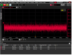
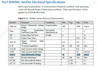
My customer is using our DS250DF410 in their switch product as the 25G optical module TX/RX. And they find when they reduce the speed of the 25G port to 1G without plugging in any modules, the serial port will print CRC messages of different ports from time to time.The main switch device is CTC8180 and the signal is normal in 25GHz and 10Ghz. But in 1G mode, the rx signal has a fluctuation of about 200mv. Is that normal? Mant thanks!

BR,

Jiaqi Wang

  • Hi Jiaqi,

    Something to note about using the DS250DF410 for 1.25 Gbps data is that it must be operated in CDR bypass mode.  Do you know if the customer is doing this?

    What is the retimer input signal when observing 200mV ouput?  Is the measurement single ended or differential?

    I also have some questions related to the system testing.  You mentioned that you start to see CRC errors without any modules plugged in.  Am I correct in assuming that without modules plugged in, there should not be any data transmitted/received and therefore no CRC errors?  If so, it seems strange that any CRC errors are observed.  Does this mean the receiver is just responding to noise?  Can you provide some more background on this so I can better understand the implications of CRC errors?

    Thanks,
    Drew

  • Hi Drew,

    Thanks for your reply! The device is already in CDR bypass mode. The reg value is here: 0xff 0x03 0xfc 0x01 0xa5 0x0 0x9 0x20 0x1e 0x89. Customer is using differential probe to test. As for the noise, the possibility of RX being affected by noise is bery low, because no sililar problems occurred in 25G and 10G modes. COuld you please help give some more comments on this? Thank you!

    BR,

    Jiaqi 

  • Hi Jiaqi,

    Can you confirm that in this test case where 200mVpp-diff is measured from retimer TX, there is no signal on retimer RX?

    The register writes you have implemented look good to set CDR bypass mode.  Can you also implement the register writes below?  You may need to adjust the EQ boost value to your use case.

    Could you share a register dump from the retimer while it is in the test case where you are observing this issue?

    Thanks,
    Drew

  • Hi Drew,

    I'm a customer of Jiaqi.We have adjust the EQ boost value.The reg value is here: 0xff 0x03,0xfc 0x01,0x31 0x00,0x1e 0x09,0x2d 0x38,0x03 0x00,0x8e 0x01,0x13 0xb0.But the CRC problem is still exist.Do you have any other suggestions?

    Thanks,

    Yingwen

  • Hi Yingwen,

    I noticed that you set CTLE boost to 0.  Is this appropriate for your system?  I would recommend reading the CTLE value that is adapted during 25G operation, then try implementing this in 1G operation and see if this improves BER.  This procedure relies on the assumption that insertion loss and transmitter settings used in 25G will be similar to those in 1G.  Do you have any additional diagnostic information we can use to debug this such as signal detect status or eye measurements?  Can you also clarify if this is for ingress or egress?

    Thanks,

    Drew

  • Hi Drew,

    We have setted CTLE boost to different value according to the table.

    But the signal waveform remains unchanged.There are four types of waveforms.


    The test point is located in the RX section of the same ds250 to the switch chip and no module is inserted into the optical port.The eye is normal after i insert module into the optical port.

    Do you have any other suggestions?

    Thanks,

    Yingwen

  • Yingwen:

        Reply may delayed due to holiday.


  • Hi Yingwen,

    Thanks for your patience, I was out of office for the holidays.

    Thank you for sharing the block diagram and scope captures, this is very helpful.  I wanted to confirm, does this only occur when the retimer is configured for 1.25 Gbps with CDR bypassed?  If CDR bypass is not enabled, does this signal go away?

    Regarding the 4 different waveforms, what is the difference between each scope capture?  Is each one a different channel?

    Thanks,

    Drew

  • Hi Drew,

    The signal is still exists after I disable the CDR bypass configured.

    About the four waveforms, before inserting the optical module, each channel corresponds to one waveform. However, after inserting an optical module and pulling it out, the original waveform may change into another waveform. We have not carried out detailed statistics on the correspondence between waveform and channel. If you need, we can do more experiments later to confirm.

    Thanks,

    Yingwen

  • Hi Yingwen,

    Can you confirm that the summary below is correct?  I would like to make sure I understand the issue you are observing correctly.

    To summarize your issue:

    • Original issue was the observation of CRC issues while retimer is configured for 1G operation.  This lead to additional investigation and observation of a signal from roughly 100 mVpp - 400 mVpp while module is not present.
    • While the retimer is configured for 10G/25G operation and no module is connected, this signal is not present.
    • While the retimer is configured for 1G operation and no module is connected, the retimer has an output from roughly 100 mVpp - 400 mVpp.  This signal is present regardless of whether CDR is enabled or bypassed.

    Have you verified that this signal is not present while the retimer is configured for 10G/25G mode with a scope?  I just want to thoroughly confirm that this is limited to 1G operation.

    I have a couple debug experiments in mind.

    1) While the retimer is configured for 1G, and a module is not present, can you check the signal detect status? This can be done by selecting one of the retimer channel registers and reading channel register 0x78[5].  I would expect this to be 0 since there is no signal present.

    2) Can you try muting the output driver and seeing if the signal is still present?  Please select a channel register set and follow the register writes below.

    3) Could you try disabling one of the channels and seeing if the signal is still present?

    Thanks,

    Drew

  • Hi Drew,

    Because of the Spring Festival holiday, I only reply you today.

    As for the points you confirmed to me, I think your understanding is correct.I'm sure these problems only occur with 1G.

    I have did the debug experiments today,the conclusion is as follows.

    1)While the retimer is configured for 1G, and a module is not present,I read channel register 0x78[5]  and found that the TX retimer 0x78[5] register value  is 0x1030 or 0x1020,the RX retimer 0x78[5] register value  is 0x1000.While the retimer is configured for 10G/25G,both TX retimer and RX retimer 0x78[5] register value are 0x1000.

    2)I try muting the output driver (0x09=0x20,0x1e=0xe0),but the signal is still present.

    3)The dignal is disappear after I disable channels.

    Whether these are helpful to you?

    Thanks,

    Yingwen

  • Hi Yingwen,

    Thanks for sharing the results of these experiments!  I'm a bit confused about your results from channel register 0x78.  This is an 8 bit register.  How are you getting 16 bits of information from it?

    Thanks,

    Drew

  • Hi Drew,

    As for the 0x78 register value, we only need to focus on the first 8 bits.

    Thanks,

    Yingwen

  • Hi Yingwen,

    Apologies for the delay.  Whenever you say we need to focus on the first 8 bits, I'm assuming you mean the 8 LSB of the 16 bit values you sent.  Please correct me if any information in my summary is incorrect.

    To summarize:

    1G Configuration (CDR bypassed), no module present

    • TX 0x78 = 0x30 or 0x20
      • Signal detected.
    • RX 0x78 = 0x00
      • Signal not detected.

    10G/25G Configuration (CDR enabled), no module present

    • TX and RX 0x78 = 0x00
      • Signal not detected.

    It seems very strange that while signal is not detected and the driver is muted, there is still an output from the DS250DF410.  Would it be possible to share a register dump from the retimer for your 1G configuration?  I would like to try to reproduce this issue.  Also, would it be possible to measure VDD and confirm that there is not any significant noise on the 2.5V rail while this issue is observed?

    Thanks,

    Drew

  • Hi,Drew,

    Your summary is correct.

    According to your requirement, I have read all the registers of DS250 in 1G mode, and see the attachment for the results. As for the 2.5V noise in 1G mode we will arrange to measure it for you later.

    DS250 register value.xlsx

  • Hi,

    Thanks for sharing the registers.  I will attempt to reproduce this in lab and will update you this week.

    Thanks,

    Drew

  • Hi Drew!

    How's the reproduction?

    Thanks,

    Yingwen

  • Hi Yingwen,

    I apologize for the delay.  I was able to replicate this.  I don't have an explanation as to why this is occurring, I'm working with my team to identify the root cause.

    If in your 1G mode, you always operate with CDR bypassed, I believe I have a suitable solution.  You can set the post lock mux setting 0xA5[7:5] = 3'b111.  This selects the mute option, which seems to eliminate the issue.  I also noticed in your registers that you shared, the pre lock mux setting 0x1E[7:5] is set to select the pattern generator.  I believe this should instead be set to 3'b000 to select raw mode.

    Thanks,

    Drew

  • Hi Drew,

    Thanks for your suggession! I try to set 0xA5 and 0x1E as your advice,but I find that  once we set 0xA5[7:5]=3'b111,the connection status of the optical module is always down.The reg value of 1G mode is here:0xff=0x03,0xfc=0x01,0xa5=0xe0,0x9=0x20,0x1e=0x03.I would like to ask if there are any other register values that need to be configured.

    Thanks,

    Yingwen

  • Hi Yingwen,

    Thanks for the update.  One alternate potential solution I observed was that leaving 0xA5 as is and toggling 0x09[5] from 1 --> 0 --> 1 seemed to stop the unexpected signal output.  Could you try this instead?

    Thanks,

    Drew

  • Hi Drew,

    I gave it a try as you suggested,I leave 0xA5=0xE0 and toggle 0x09 from 0x20 -> 0x00 -> 0x20,but the problem is still alive.

    Thanks,

    Yingwen

  • Hi Yingwen,

    Thanks for the update.  This is a bit surprising since this seemed to resolve the issue when tested on the bench.  Are you still measuring the retimer output with a scope similar to your previous scope measurements?  Can you also confirm that when 0x09=0x00, the retimer output is muted?

    Thanks,

    Drew

  • Hi,Drew,

    I used the same measurement method as before.Once I put 0xa5=0xe0, there is no signal from the retimer output, whether or not I am plugged into an optical module,as if the retimer was off.Do you have any ideas?

    Thanks,

    Yingwen

  • Hi Yingwen,

    Thanks for clarifying.  I will spend some more time in lab reproducing this and trying to find a better solution.  Thanks for your patience.

    Thanks,

    Drew

  • Hi,Drew,

    How's the reproduction?

    Thanks

    Yingwen

  • Hi Yingwen,

    Apologies for the delay.  Can you try setting the following?

    0x1E[7:5] = 3'b000    # Sets pre-lock output to raw

    0xA5[7:5] = 3'b001 or 3'b000    # Sets post-lock output to mute or retimed data

    0x09[5] = 1'b0    # Must be set to 0 for 0x1E[7:5] to take effect.

    Thanks,

    Drew

  • Hi Drew,

    We have try the register value today,but the CRC problem is still exist.The register value is here:0xff=0x03,0xfc=0x01,0xa5=0x00,0x9=0x00,0x1e=0x03.

    Thanks,

    Yingwen

  • Hi Yingwen,

    Thanks for the update.  Just want to clarify, with these settings, do you observe an output of 1G data from the retimer?  Does it still have the noise you were observing before?

    In my testing, I had found that setting 0x09[5] = 1'b0 removed the "noise" issue that we had observed and also allowed data to pass through the device.  It would be valuable to understand if the CRC issue exists independently from whether the signal is clean.

    Thanks,

    Drew

  • Hi Drew,

    My test results show that 1G signal output is normal, but the noise was the same as I had seen before.

    Thanks,

    Yingwen

  • Hi Drew,

    I would like to ask if we have any other experiments on this issue?

    Thanks,

    Yingwen

  • Hi Yingwen,

    Apologies for the delay, somehow I missed your prior response on this thread.

    I know this issue has been ongoing for some time, so I wanted to re-align on the issue.  My understanding is that when the retimer is configured in CDR bypass mode, if there is not an input present, noise will be observed on the retimer output.  Is this correct?

    Could you share your most recent register settings?

    Thanks,
    Drew

  • Hi Drew,

    There is no problem with your understanding, the problem now is that there is an abnormal waveform in the output without input.

    See attachment for the latest register list.The yellow padding is not the only value.

    Thanks for your help!

    Yingwen

    DS250_register.xlsx

  • Hi Yingwen,

    Thanks for sharing the register dump.  I will try to reproduce this with your registers.

    Thanks,
    Drew

  • Hi Yingwen,

    Thanks for your patience on this.  I tried testing with your register dump.  While I did observe some output noise using your register dump, it was identical to the noise seen in a generic CDR bypass configuration.  It also had a much smaller amplitude than I had observed in the past, so I think this level of noise is inherent to the device when no input is present.

    Regarding the CRC issue, I'm wondering if there might be some other issue besides the device noise.  Have you tried measuring BER of the channel?  Can you share more about what criteria are required to get a CRC error message?

    Thanks,
    Drew

  • Hi Drew,

    I checked the datasheet of the switch chip, and as long as the RX differential signal swings more than 50mv, it may be considered a signal.So I want to know if the noise swing you measured is more than 50mv.


  • Hi,

    I believe we measured around 40-60mV, although some of this was observable on the scope with no input.  Even if we meet "signal detect" criteria, I would not expect noise to create a CDR lock condition on the switch chip.

    In general, we would also expect signal amplitude to far exceed any noise.

    Have you tried any BER measurements using a PRBS pattern?

    Thanks,

    Drew