This thread has been locked.

If you have a related question, please click the "Ask a related question" button in the top right corner. The newly created question will be automatically linked to this question.

MAX3243E: No output

Part Number: MAX3243E

Hi TI Teams,

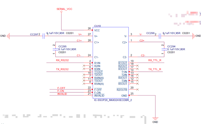
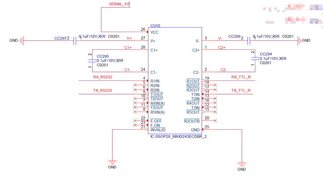
Our new project using MAX3243E for serial port conversion, but found that there is no output when the signal input.

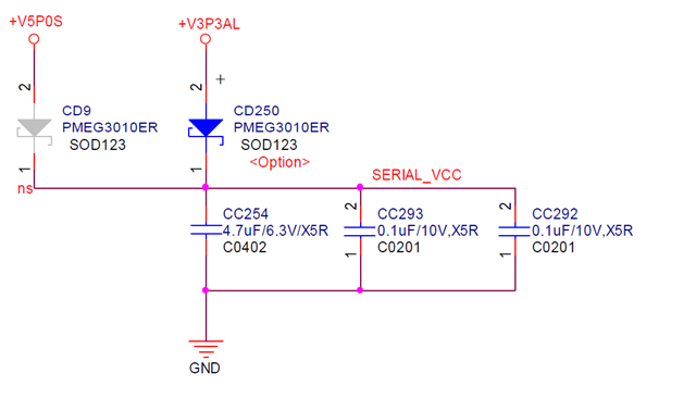
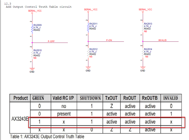
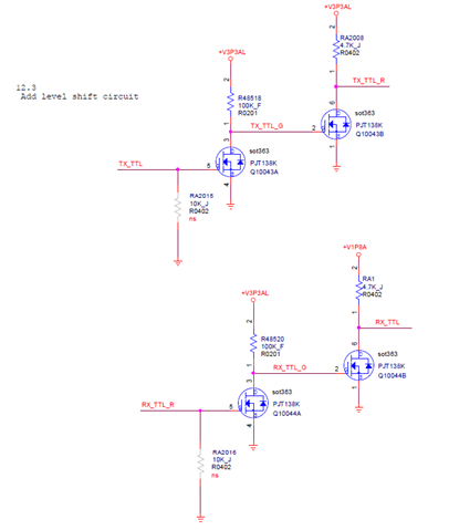
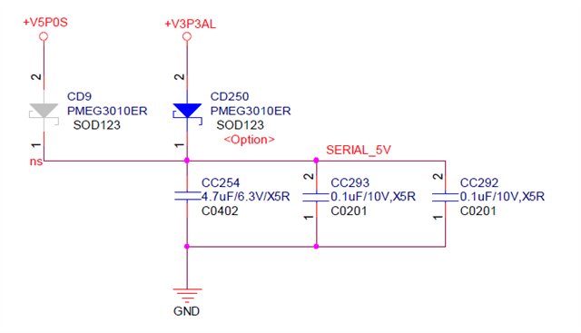
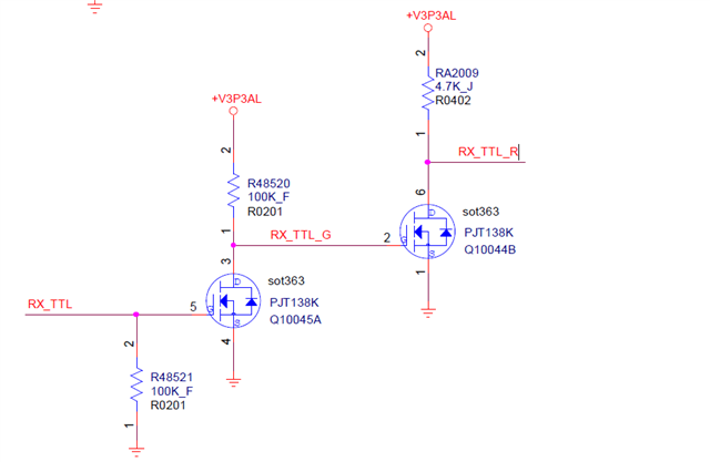
The schematic is show as below:

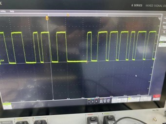
The waveform of input is as below:

Thanks,

Kind Regards

  • It's likely that the device is in power-down mode. Digital inputs (pins 12, 13, 14) and especially control inputs (pins 22, 23) must not be left floating.

    And I do not understand why Q10044B is connected to an output pin.

  • Hi Lumina,

    The FORCE pins as well as the digital input pins (the ones Clemens also noted 12,13,14, 22, and 23) must not be left floating or you could experience application issues as the device is in an indeterminate state.

    Please let me know if you have any other questions.

    Best,

    Parker Dodson

  • Hi Parker,

    Thanks a lot. And we will redesign the circuit according to your suggestion and testing.

    Best Regards

  • Hi Parker,

    We have redesign the circuit, can u help to check it?

    Thanks,

    Kind Regards

  • Hi Lumina,

    The changes that you have made should keep the device state known which should help mitigate at least some of the issues that you are seeing.

    With that being said:

    T2In and T3IN should be shorted to ground or VCC. Even though T2OUT and T3OUT are not connected either when you have console side data input pins (TXIN for many devices) and they are left floating they can have few negative effects on the system even if the corresponding outputs are not connected:

    1. Floating inputs can cause much large power consumption as floating voltages can cause the logic circuit to create a relatively low impedance path to ground which also could cause some oscillations on the power line due to the inductance of the line.

    2. If the input is floating the corresponding output could glitch (oscillate) and since the pin is not connected to anything it can act as an antenna with the glitchy signal from the floating input pin. 

    If you ground or connect VCC to T2In and T3IN there will be minimal current draw from the internal logic circuits attached to these pins, less chance of power line oscillations, and the output pin won't have an alternating voltage on it making it much less prone to negatively impact the other parts of the circuit. 

    The system may work without grounding those pins but it is advisable to make those connections to help prevent potential failure conditions. 

    Please let me know if you have any other questions!

    Best,

    Parker Dodson