This thread has been locked.

If you have a related question, please click the "Ask a related question" button in the top right corner. The newly created question will be automatically linked to this question.

TCAN1043G-Q1: input capacitance to gnd measurement setup and process

Part Number: TCAN1043G-Q1
Other Parts Discussed in Thread: TCAN1043-Q1, , TCAN1043A-Q1

Hi team,

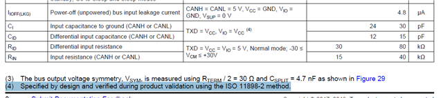
VW required my customer to test the Ci (input capacitance to gnd) of TCAN1043G before they approve it for mass production, VW's requirement is smaller than 47pf, can you share more guidance on how to validate this spec by customer?

Including: bench setup, equipment, test process etc.

Regards,

Dongbao

  • Dongbao,

    The TCAN1043-Q1 and TCAN1043G-Q1 will not receive increasing supply to support new projects over time. The successor to this part is the TCAN1043A-Q1, which can fit in the same socket and has improved performance. It will also have increasing supply over time to support new projects in our newest process technology.

    Pin capacitance to ground on TCAN1043A-Q1 is less than 20 pF for CANH/CANL, and differential input capacitance is less than 10 pF.

    Best,

    Danny

  • Danny,

    Thanks for your suggestion on promoting A version.

    Then the questions is still the same, how to TEST the pin capacitance to ground? No matter which TCAN104x, i believe the test setup and procedure doesn't change. pls support this specific request

    Dongbao

  • Dongbao,

    The CANH and CANL pins are more of a complex system than a simple capacitor to ground. In addition, there are leakage currents into/out of the pins, and there is active biasing to VCC/2 for both pins. One method I recommend would be first to use a series resistor to measure leakage current into CANH. This can be accomplished by measuring the drop across a resistor (i.e. 1 kΩ or 5 kΩ). You need to account for this resistance when determining your capacitance using a discharge curve, otherwise you will underestimate resistance, leading to an overestimate of capacitance.

    After determining this resistance factor, I'd recommend connecting CANL to ground, followed by applying a test square wave and measuring the rise/fall time across a test resistor for CANH. Then, when calculating, exclude the leakage path determined above from your calculation.

    Simply executing a standard rise/fall time measurement (like an LRC meter might do) would potentially cause an overestimate of capacitance, but could still work as a quick test if there is margin in the system.

    Best,

    Danny