This thread has been locked.

If you have a related question, please click the "Ask a related question" button in the top right corner. The newly created question will be automatically linked to this question.

DS90UB960-Q1: The IIC read command data forwarding in 960 and 935 is abnormal

Part Number: DS90UB960-Q1
Other Parts Discussed in Thread: DS90UB953-Q1

Dear sir,

We have a problem where the host needs to detect the status of the camera by reading the value of a register iin camera ISP, the ISP address is 0x300A. the normal value is 0x04 to report whether the camera status is normal. Within 5 to 10 minputes after power-on, this register value will be changed.According to the IIC data caught on the camera side, there are write operations on this register on the bus, while there are no write commands on the host side.

Below is the abnormal IIC data captured by the camera side:

194,13937618500.00000000000000000000,Start
195,13937705300.00000000000000000000,Write
196,13937629300.00000000000000000000,Address write: 24 
197,13937716100.00000000000000000000,ACK
198,13937753200.00000000000000000000,Data write: 30    <-------------- To read ISP writes 0x300A to 0x24, this looks normal.
199,13937840100.00000000000000000000,ACK
200,13937876800.00000000000000000000,Data write: 0A
201,13937963700.00000000000000000000,ACK
202,13940335600.00000000000000000000,Data write: 30  <--------- But here it's going to write 30, which means write 30 to 0x300a.
203,13940422400.00000000000000000000,ACK
204,13940482200.00000000000000000000,Stop
205,14135539400.00000000000000000000,Start
206,14135626200.00000000000000000000,Read
207,14135550200.00000000000000000000,Address read: 24
208,14135637100.00000000000000000000,ACK
209,14135647900.00000000000000000000,Data read: FF
210,14135766600.00000000000000000000,NACK
211,14135783000.00000000000000000000,Stop
212,15179508500.00000000000000000000,Start
213,15179595400.00000000000000000000,Write
214,15179519400.00000000000000000000,Address write: 24
215,15179606200.00000000000000000000,ACK
216,15179643300.00000000000000000000,Data write: 30  <--------- Then you read 24 and it's always going to be 30.
217,15179730200.00000000000000000000,ACK
218,15186252500.00000000000000000000,Stop

Best regards

  • Hello Li,

    the SER or DES do not do any I2C writes standalone. The I2C Master on the DES side, or any other I2C device on the bus, must be doing these write attempts!

  • Hi Hamzeh,

    Yeah, that's right, SER or DER will not do any IIC writes., as I said at the beginning, there are no write commands on the host side. I mean that maybe the FPD-Link forwarded the mainframe data by mistake. The address of the target register in question is 16-bit. From the above data, when reading this register, the write command is followed by the write instead of read 300a. I think even if there are other devices occupying the IIC bus, it should not be the same time to write command instructions after the write 300A.

    Best regards

  • Hello Li,

    Do you have Pass-Through-All enabled on the DES register 0x58? If not, maybe the way you are targeting the 16-bit address is confusing the DES because the part of the I2C address = 0x30 is equal to an Adress of the SER or one of the Slaves on the Camera?!!

    Normally if we want to write to a 16-bit address, for example the Slave address is 0xC4 and the register address you want to write to is 0x3129, we use this command to write the value 0x80:

    board.WriteI2C(0xC4, 0x31, [0x29, 0x80])

  • Hi Hamzeh,

    No, not yet. I dump the value of register 0x58, the IIC Pass-Through All Transactions is disabled. 

    I don't quite understand the meaning of this sentence “maybe the way you are targeting the 16-bit address is confusing the DES because the part of the I2C address = 0x30 is equal to an Adress of the SER or one of the Slaves on the Camera?!!”, can you rephrase it?

    And also, as you said, what if I want to read a 16-bit address register?

    BR

  • Hello Li,

    what I wanted to say is that the way you are writing, or reading is not compliant. We use a different format once we want to write or read into a 16-bit address. The used format is:

    board.WriteI2C(0xC4, 0x31, [0x29, 0x80])

    board.ReadI2C(0xC4, 0x31, [0x29])

    where Slave address is 0xC4, register address is 0x3129, the register value is 0x80:

  • Hi Hamzeh,

    This is not an inevitable problem, if it is out of order should not happen by accident. We use the standard IIC read and write interface, Qualcomm platform also supports 16 bit address read and write.

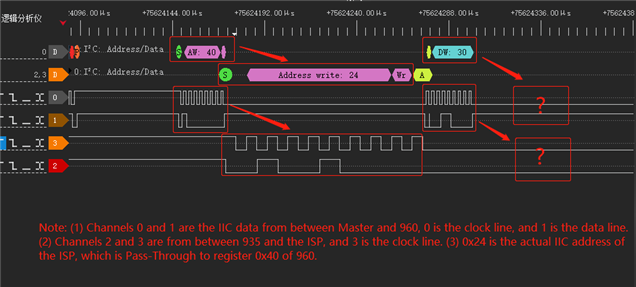
    The picture below is a set of data before the exception occurred. It can be seen that when the host wrote 30, the slave did not receive it. I think this is the direct cause of the problem.

    BR

  • Hello Li,

    Thanks for the clarification.

    Do you see CRC errors on the SER registers, 0x52, 0x55, 0x56?

  • Hi Hamzeh,

    As shown in the screenshot.

    In addition, I cleared the values of 0x55 and 0x56 and read them again, immediately increasing to FF.

  • Hi Li,

    That indicates you have a massive Back-channel problem, which clarifies why you are missing some I2C packets over the back-channel.

    Please check you link quality (Cable, connector, layout and PoC Filter) and make sure these have good performance at the back-channel frequency range, which is between 5MHz to 50MHz, depending on the Mode you are using!

  • Hi Hamzeh,

    I'm not sure whether the Back-Channel link quality you mentioned will affect the normal image production of the camera. The image is normal when this problem occurs. I also want to ask:

    (1) How to measure the link quality, is there any tools can detect it? Is it like the eye diagram?

    (2) Is this frequency range determined by configuring the value of the register 0x58 of ti960? I dumped out it was 0x5e at present.

  • Hello Li,

    For measuring forward channel link quality, you can use the MAP tool: 

    https://www.ti.com/lit/pdf/snlu243

    https://www.ti.com/lit/pdf/snla301 

    For back channel link quality, you can continuously monitor the CRC error count in the DS90UB953-Q1 (registers 0x55 and 0x56). Make sure to clear the CRC error count after initialization to cover any transient errors. There is no eye diagram tool for the back channel. Since the error count is maxing out, it seems there are significant back channel signal quality issues. Are you using PoC on this application? Does the PoC network match the recommended network from the datasheet?

    The frequency of the back channel is set by 0x58 on the 960 as you say. You are currently using 50MHz back channel which has a low end frequency of 25MHz 

    Best Regards,

    Casey 

  • Hi Casey,

    Thank you very much for your answer. The POC was used for this project. Actually, I don't know if 50MHZ is appropriate. The code does write this register as 0x5e. Do I need to change the value of this register to test it?

    BR

  • Hi Li,

    Thanks for your question. Due to US holiday, we resume activity and provide feedback on 12/28. Thanks for your patience.

    Regards,

    Logan

  • Hello Li,

    It depends on the Mode you are using on SER and DES! Can you send me your schematic for SER and DES for review and checking which mode are you using?

  • Hi Hamzeh,

    I only have the schematic of 960, and the schematic of SER is with the camera manufacturer. If you must need it, I can ask for the camera manufacturer.

    In addition, I am very sorry that I can only provide the connection diagram of part of the pin for confidentiality reasons. Can you tell me which pin you want to know?

    BR

  • Hello Li,

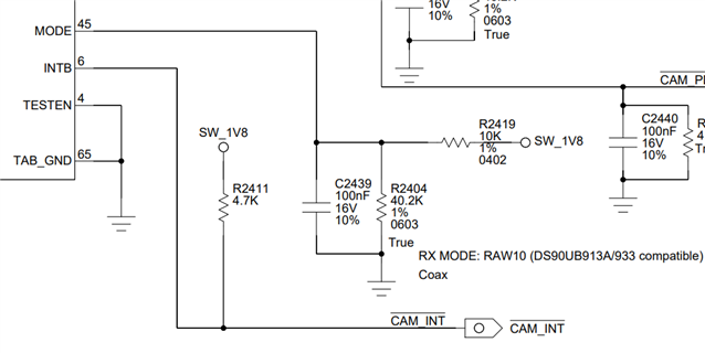
    I need to see MODE pin connection, on both devices, SER and DES.

  • Hi Hamzeh,

    The following is the schematic diagram of DES.

    For SER, they only provide text description, please understand.

    "Pull up 75K resistor and pull down 35.7K resistor, CSI-2 Non-synchronous clock – FPD-Link III Clock reference derived from external clock reference input on CLKIN pin."

    BR

  • Hello Li,

    Looking at the provided details, it looks like you are using a non-valid Mode on the 954 device. There is no such resistor combination in Table 2 on the d/s with 10K pull-up and 40K pull-down.

    Also, you must use the exact same Mode on both devices. If your SER is setup to work in CSI-2 Non-synchronous clock Mode, then your DES must be in the same mode. So, your resistors must be OPEN and 10Kohm pull-down. If you want to set that using registers, then you must write reg 0x58 = 0x5A.

  • Hello Hamzeh,

    Great ! The problem seems to have been solved by changing the value of the 0x58 register to 0x5a. I also want to know, write reg 0x58 = 0x5a, isn't this set Back Channel Frequency Select to 10Mbps?

    Why did you look at the DES and SER schematics and conclude that the frequency should be set at 10Mbps? You mentioned above that DES and SER should be in the same mode, but 0x58 seems to be independent of the configuration of the mode, can you help with the confusion?

    BR

  • Li,

    In non-synchronous mode, the SER only support 10Mbps back channel rate, not 50Mbps:

    Best Regards,

    Casey 

  • Hello Casey,

    Hameh said before that the modes on both sides should be consistent, but now there is no configuration about DES mode. Does 10Mbps represent asynchronous mode?

    In addition, after the configuration is set to 10Mbps, from the values of 0x52, 0x55 and 0x56, there is still a massive Back-channel problem analyzed previously,is this normal?

    BR

  • Hello Li,

    Yes, for Non-Synch Mode you only should use the 10Mbps BC speed.

    In addition, after the configuration is set to 10Mbps, from the values of 0x52, 0x55 and 0x56, there is still a massive Back-channel problem analyzed previously,is this normal?

    As I said earlier, that indicates you have a massive Back-channel problem! You should check your link quality (Cable, connector, layout and PoC Filter) and make sure these have good performance at the back-channel frequency range, which is around 5MHz for Non-Synch Mode!

  • Hello Hamzeh,Casey,

    Thank you very much for your support !

    BR