Hello E2E Experts,
Good day.
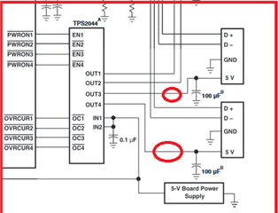
Is it possible to review my attached schematics for your TUSB2036?
The 2 downside devices (Quectel EC25 and Fanstel BT840X) are permanently attached through PCB traces but they can be powered off when not used. That's why I've tied NPTINT0/1 to GND.
The 2 downside devices are powered through a Meanwell PSU for +5V and an LDO for +3.3V. So not from VBUS as the Quectel EC25 can peak at 2A.
The upside of the TUSB2036 is attached to a 5cm USB cable coming from a Raspberry Pi 3A+ which is also on the same PCB.
I trick OVRCUR1/2/3 by tying them to +3.3V and letting PWRON1/2/3 floating as suggested by someone.
Questions :
1) Do I need to add 15k pull-up resistors to unused OVRCURx pins as suggested here https://e2e.ti.com/support/interface-group/interface/f/interface-forum/1074483/tusb2036-schematic-review?tisearch=e2e-sitesearch&keymatch=tusb2036# ?
2) As my device are not powered from VBUS, I assume I'm in "self-powered" mode. Right?
3) Is the NPINT0/1 configuration correct in my design?
4) Is there anything else wrong I've not seen yet?
PS: I've tried to submit this on the forum but I've spent an afternoon trying to login on my account to find out it was deleted and now that I can connect again, I can't display the form to post. Tried on Firefox/Chromium/Edge.
Attached herein is the schematic.
Thank you in advance for your support.
Regards,
CSC


