This thread has been locked.

If you have a related question, please click the "Ask a related question" button in the top right corner. The newly created question will be automatically linked to this question.

SN65HVD1791: Some Inquiries

Part Number: SN65HVD1791
Other Parts Discussed in Thread: ISO3082, , ISO3080

Hello Expert,

There may be some unreasonable part in my question, so please forgive me.

Our customer is under design w/ this part.

This application is fire alarm system and communicate RS-485 between main receiver and other local receivers.

Here is my questions.

1. If RS485 communication (full duplex) needs to be done up to 3km, can I use a repeater or amplifier in the middle?

    Please introduce a circuit diagram or parts that you can recommend. also share app. note.

2. If we use full duplex, What are the specifications of the wire?

3. If one main fire receiver and 13 local fire receivers are connected,

    Do we need separate control to communicate for data transmission?

    Or is it possible to communicate by automatically checking the line in the communication chip?

4. Communication distance (1km) If the total data communication amount is 93,600 bytes, what is the communication processing time?

5. Do you have reference circuit design data?

Best regards,

Michael

  • Michael,

    Thanks for posting, and don't worry about asking questions - that's what this forum exists for!

    Please allow us some time during the holidays, during which time our responses will be delayed. We will address your questions as soon as we are able.

    In the meantime, have a happy holiday season.

    Best,

    Danny

  • HI Michael,

    I apologize for the delay - I was out of the office for the last two weeks. I am sorry for any inconvenience this may have caused!

    1. I would suggest 2 RS-485 repeaters (1 at 1km and 1 at 2km - as max is about 1.2km without repeater (at 100kbps))  - we have an excellent application note: https://www.ti.com/tool/TIDA-00333#applications. A few notes - this is specifically for half duplex - but it is the closest application diagram we have - there would have to be a few modifications - but they are pretty simple to make.

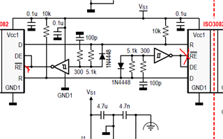
    In the app note an isolated half duplex device is used the ISO3082 - but the architecture can be used for any RS-485 device. However Isolated RS-485 transceivers make good parts for repeaters as it will also isolate the ground pathway and block large DC offsets on the ground line - we do have full duplex isolated options available: https://www.ti.com/interface/rs-485-rs-422/products.html#p1065=Full&p1690=Yes&sort=p1692;asc - the ISO3080 is essentially the full duplex version of the ISO3082 so it can be used as the repeater. Isolated repeaters are going to help reduce the ground potentials seen at either end of bus - the more repeaters - the more benefit. This isn't seen if you used  SN65HVD1791 based repeaters (which is possible) as the ground potential difference is going to based by how much current is going through the ground wire + distance + resistance/unit length of cabling. The SN65HVD1791 is fault protected up to +/-70V but its common mode -20V to 25V - where the common mode range is operational range and beyond that operation is guaranteed (but the device is still protected from damage up to +/-70V on its bus pins) - so if you think the Ground potential difference of the bus over 3km is going to be outside of the range -20V to 25V - I'd strongly advise an isolated device as the repeater. 

    For modifications all you really need to do is connect /RE to GND instead of the output of the Schmidt trigger this way the device will always be listening on its RX pins and will turn on the TX pins whenever a signal comes into the device. I have shown red x's on pins that shouldn't be connected as shown in app note for full duplex. /RE should be grounded not connected to output of Schmidt Trigger  buffer


    However if the distance between each node is < 1.2km then each node can be daisy chained together (output of first node is input of second node.... etc...) you still may need a repeater to complete the bus from last output to first input. This will allow potentially less repeaters in the overall design. Please note however that if you daisy chained as explained above it may be best to terminate every bus segment as if it's its own independent bus. In this case terminating only the input is okay to reduce cost. This method will not  the ground potential differences as much as a isolated repeater design would (which at 3km - I'd suggest isolated if at all possible) 

    2. For the signal wire it is always suggested to be twisted pair 120 Ohms if possible - with each end of bus being terminated with 120 Ohms. This means the repeaters will be terminated as well as the first node in the chain and the last node as each repeater essentially creates a new bus. In generally though 120 Ohm characteristic impedance cable for data signals is fine to help prevent  Signal quality decay as much as possible Nodes should be daisy chained together or use junction boxes with a spine for the topology.

    3. IN this application each RS-485 device has 2 control pins - the /RE and DE pins. The repeater design controls itself (its always listening and when it receives data it will transmit it out the drive pins when message is received). The device specific nodes may need to have a control scheme to toggle the driver or receiver on or off - but it is very common in RS-485 applications to keep /RE pulled to ground and using 1 control pin to toggle DE on or off - so that it can be turned off when not communicating to prevent it signaling. As far as software goes - that's dependent on the data protocol you use - RS_485 is protocol independent

     4. It depends heavily on the software, topology used, and devices chosen. 

    Assuming that you use all SN651791's for the repeater as well as daisy chained with 2 repeaters in the system maxing out at 100kbps. The worst case is when the two devices on each end of bus (one at x = 0m and one at x = 3000m) 

    delay = T_process_software_tx + (14 * Tprop_RX_SN65HVD1791 )+ (14 * Tprop_TX_SN65HVD1719) +  2*repeater_delay  + signal_propagation_delay  + device_processing+data_length_delay

    Tprop_RX_SN65HVD1791 (worst case) = 200ns

    Tprop_TX_SN65HVD1791 (worst case) = 2us

    repeater_delay = 1 RX + 1 TX  ~ 2.2us 

    process_software_tx = dependent on controller firmware - not RS-485 hardware

    device_processing = dependent on top level firmware for device bus is connected to - not bus itself.

    signal_propagation_delay = 3000 * c *  v where c is speed of light and v is the signal propagation (usually expressed as a percentage like 70%) 

    data_length_delay = total number of bits / data_rate --> 93.6k / 100kbps = 0.936 seconds

    So we can basically break teh equation down into cable delays, data delays, transceiver delays, and firmware/controller delays. 

    Processing Time = Cable_Delay + Data_delay + transceiver_delay + firmware/controller delays

    Cable_delay = depends on cabling used - 'v' should be spec'd in cable datasheet

    Data_delay = 0.936seconds at 100kbps (this speed maxes out bus length - its slightly slower than the HVD1791's max data-rate so it may be able to be pushed a bit) 

    transceiver delay = 38us + 3.8us + 4.4us = 46.2us

    firmware/controller delays - this is dependent on the hardware controlling the transceivers and the firmware stack used - this is most likely going to be one of the longer steps as the physical speed isn't the biggest issue - the cable delay and transceiver are generally pretty quick when looking at data length time. The firmware may slow this down. 

     Processing time = 0.9360462 seconds + cable delay (should be pretty short) + firmware/controller delays (this is variable and could be long) 

    the hardware (minus the cable delay) is <0.005% of the data length so it adds a very small delay to the actual message - the firmware processing could be time consuming but that is not dependent on the transceivers themselves. 

    5. The refence design is linked in point 1 - the modifications are explained in point 1 as well to make it full-duplex. 

    Please let me know if you have any other questions and I will see what I can do!

    Best,

    Parker Dodson