Part Number: TUSB212
Hi
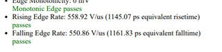
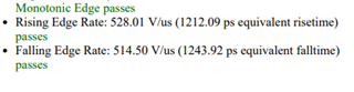
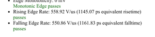
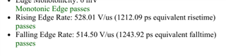
My customer had measured the USB bypass mode and redrvier mode, and found the rising/falling time of the bypass mode is better, does it make sense?
Far End High Speedtest results for L1_60mV.pdfFar End High Speedtest results for A01-bypass.pdf