This thread has been locked.

If you have a related question, please click the "Ask a related question" button in the top right corner. The newly created question will be automatically linked to this question.

TIOL111: Query related to switching of CQ line of TIOL111 without LDO part

Part Number: TIOL111

Hello,

I am using TIOL111 (without an internal LDO) part in my design. 3.3V Input for TIOL chip is generated externally by DC/DC buck converter IC (LMR14010) with input +24V.

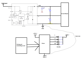
Application : I am driving 50 numbers of LEDs with the help of IO-Link Master. [Please refer below picture for reference]

IO-link master sends command to TIOL chip -> the TIOL chip is interfaced with the "Driving and controlling circuit" block -> Driver makes required LEDs ON or OFF.

TIOL chip's "GND" and Driver IC's "GND_1" are shorted with "short Link".

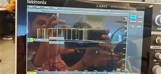
Issue 1 -> In above scenario, When IO-link communication between Master and TIOL chip is made ON, i am seeing fluctuations on GND and GND_1 lines. [Peak to peak around 7V]

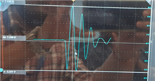
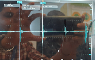
Occurrence of such fluctuations are typically after 4.2usec (around 230.4 kHz which is baud rate set for IO-link communication in my design)

When IO-link communication is stopped, the above fluctuations are gone (peak to peak voltage reduced to mV)

Issue 2 -> When I make all the 50 LEDs ON and OFF by 1 sec, I am seeing My DC-DC output swing from 3.212V to 3.479V. i.e. when all 50 LEDs are ON, DC/DC output is 3.479V and when they are OFF, output drops to 3.212V. When less number of LEDs are ON (say 4 or 5) or If LED's are ON in scrolling fashion (1 LED is ON at a given time), This swing in DC/DC supply output is not observed.

Question is -> What could be the reason of above 2 issues ? Any idea to resolve such issues ?

Regards,

Prasad

  • Hello Prasad,

    Issue 1:

    The issue you are seeing is likely the result of inductive ringing on the CQ and GND lines between the IO-Link Master and the TIOL111 device. 

    How long is the cable between the Master and the TIOL111 device?

    Have you monitored the CQ data line for ringing as well?  If so does it correlate to the ringing observed on the GND?

    Is there ringing only when the Master sends data to the TIOL111 device, only when the TIOL111 device is sending data to the Master, or when either the Master or TIOL111 is sending data? 

    Issue 2:

    This Interface Forum is for the TIOL111 support and I am not an expert on the LMR14010.  I would suggest you post a question using this part number to get specific support on the LMR14010. 

    However, briefly looking through the LMR14010 datasheet and your observations of a voltage drop at low current (no LEDs ON), it sounds like the voltage change may be due to the LMR14010's EcoModeTm.

    I noticed that the the LEDs and LED driver is coming from a different 24V supply (+24V_1) than the TIOL111 (+24V).  How are these two 24V supplies related?  Are they completely independent of each other, or are they somehow connected with a common source or cable?

    Regards,

    Jonathan

  • Hello Jonathan,

    Thanks for your reply !

    Below are the answers to your questions in Blue color text  ->

    Issue 1:

    The issue you are seeing is likely the result of inductive ringing on the CQ and GND lines between the IO-Link Master and the TIOL111 device. 

    How long is the cable between the Master and the TIOL111 device?  -> Cable length is around 1 to 1.5 feet

    Have you monitored the CQ data line for ringing as well?  If so does it correlate to the ringing observed on the GND?

    -> Yes I have monitored CQ data line. But, CQ data line doesn't show such ringing. CQ line waveform is captured below-


    Is there ringing only when the Master sends data to the TIOL111 device, only when the TIOL111 device is sending data to the Master, or when either the Master or TIOL111 is sending data?

    -> Ringing is observed during IO-link communication between Master and TIOL device. It is not dependent as such on who is sending or receiving data.

    Issue 2:

    This Interface Forum is for the TIOL111 support and I am not an expert on the LMR14010.  I would suggest you post a question using this part number to get specific support on the LMR14010.  -> Ok. I will raise separate question. 

    However, briefly looking through the LMR14010 datasheet and your observations of a voltage drop at low current (no LEDs ON), it sounds like the voltage change may be due to the LMR14010's EcoMode.

    I noticed that the the LEDs and LED driver is coming from a different 24V supply (+24V_1) than the TIOL111 (+24V).  How are these two 24V supplies related?  Are they completely independent of each other, or are they somehow connected with a common source or cable?

    -> In this case, both of these supplies (24V and +24V_1) are coming from different sources but, their GND's are made common on my PCB.

    In another case, both of these supplies will be taken from same source. so, no need to make their GND's common on my PCB.

    But, in both the cases ringing noise is present.

    Thanks and regards,

    Prasad.

  • Hello Prasad,

    Thanks for the additional information.  I have a few additional questions about the test setup.

    Where in the circuit diagram you provided are you making the scope measurements, and do the results change in any way by measuring in different locations such as the GND reference on one board vs. the other board?

    If you are using the scope probe to measure the GND signal, what is the scope probe's GND reference connected to?  Where in the circuit is it connected, or is it left floating?  Typically the scope probe reference is connected to GND. 

    If the probe tip and reference are both connected to GND, then I would not expect to see a large voltage variation.  But if the reference is floating, the scope probe doesn't have a good reference and some of this ringing could be from the test setup itself.

    However, I'm not suggesting this is just a test setup issue.  The ringing has a classic inductive ringing and natural decay profile common with sudden changes in impedance on transmission lines. 

    The basic equation for the impedance is √(L/C) where the inductance and capacitance of the cable has some frequency response.  When there is no communication and the line is idle, the drivers are typically "off" and are in a high impedance state.  When there is communication, the drivers are "on" and create a low impedance state either between the 24V supply, or GND to generate the data. 

    This changing impedance can result in a high frequency pulse of energy that travels down the cable and bounces back and forth between the two end of the cable.  Each trip causes the amplitude to decay through the parasitic losses in the cable and any current absorbed by the devices at the two ends of the cable. 

    From the timestamps of your scope plots, it appears the ringing noise appears every bit transition in the data.  Since the data is between the CQ and GND pins, you could try to add some capacitance between these two pins to act as a small decoupling capacitor and stabilize the transitions. The extra capacitance will help slow down the rise/fall times and filter out some of the higher frequency content, basically a low pass filter.

    Adding a series resistor is a common source termination technique by speeding up the time needed to decay the reflected energy.  This doesn't prevent the ringing, but it helps to reduce the amplitude and time duration.

    Have you monitored the 24V supply for any ringing noise? Because the IO-Link drivers switch the CQ between the 24V and GND rails, there is a change in current draw on the supply between 24V and GND for each bit.  You will want good decoupling capacitance on the 24V supply on both sides of the cable.  If you only have a single 100nF decoupling capacitor between 24V and GND on the TIOL111 side of the cable, you will want to add more capacitance such as 2.2uF, 4.7uF, or 10uF as an example in addition to the 100nF.  It is possible the 24V supply voltage is also fluctuating as it tries to source the current through the inductive cable.  This could cause the GND to fluctuate with it since it is a potential difference between the two.

    Regards,

    Jonathan