This thread has been locked.

If you have a related question, please click the "Ask a related question" button in the top right corner. The newly created question will be automatically linked to this question.

DS90UB948-Q1: test pattern mode

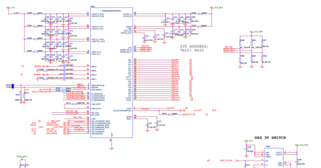
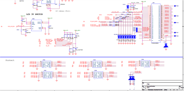
Part Number: DS90UB948-Q1

Dears:

  When we output the white and green patterns in the test pattern mode, it is normal, but the blue and red patterns turn to purple. There is no short circuit between the check channels.What else might cause this?


  • Hello,

    It sounds to me like possibly the polarity of the OLDI clock lane was flipped? P/N are reversed?

    Best Regards,

    Casey 

  • Hello,

    We have confirmed that the clock polarity is correct.

  • Hello,

    Can you please send over the datasheet for the display panel here?

    Best Regards,

    Casey 

  • Hello,

    I don't see any obvious reason why the colors could be changed other than the clock polarity. Have you tried enabling the different MAPSEL settings in the 948? Based on your panel spec you should be using MAPSEL = H, but you could also try MAPSEL = L? 

    Can you share the script you are using to enable PATGEN? Maybe the video timing has an error? Are you generating PATGEN directly from the 948? Or from a serializer attached to the 948? 

    948 will not be able to directly generate the exact timing for this panel which may be part of the issue. The maximum PCLK that 948 can generate is ~140MHz (70MHz per channel) but the exact PCLK rate is not well controlled (very high variation unit to unit). Can you measure the PCLK rate that you are getting from the 948?

    Best Regards,

    Casey 

  • 1. We tried using MAPSEL=H or L ,but it didn't change.

    2. We generated PATGEN directly from the 948. Script is shown as below:

    int ds90ub948_des_testpattern_init(void)
    {
        cy_en_scb_i2c_status_t  result_i2c;
        //a:1920*1080   total:2040*1114  hbp:80  hfp:40  hpw:20  vbp:10  vfp:24  vpw:2  vs_hs_pol:Negative
                            //PGIA  PGID    PGIA    PGID    PGIA    PGID    PGIA    PGID    PGIA    PGID    PGIA    PGID    PGIA    PGID    PGIA    PGID    PGIA    PGID    PGIA    PGID    PGIA    PGID    PGIA    PGID            PGCFG   PGCTL
        uint8_t reg_addr[] = {0x66, 0x67,   0x66,   0x67,   0x66,   0x67,   0x66,   0x67,   0x66,   0x67,   0x66,   0x67,   0x66,   0x67,   0x66,   0x67,   0x66,   0x67,   0x66,   0x67,   0x66,   0x67,   0x66,   0x67,           0x65,   0x64};
                                //(clk需要重新配)                                                                                                                                                                                这里可能错需要测试不行就用0x5
                            //PGCDC ClK_Div PGAFS1  AHW     PGAFS2  AVW_AHW PGAFS3  AVW     PGTFS1  THW     PGTFS2  TVW_THW PGTFS3  TVW     PGHBP   HBP     PGVBP   VBP     PGHSW   HSW     PGVSW   VSW     PBSC    VS_POL_HS_POL   
        uint8_t reg_data[] = {0x03, 0x02,   0x07,   0x80,   0x08,   0x87,   0x09,   0x43,   0x04,   0xF8,   0x05,   0xA7,   0x06,   0x45,   0x0C,   0x50,   0x0D,   0x0A,   0x0A,   0x14,   0x0B,   0x02,   0x0E,   0x03,           0x06,   0x31};
      
        int i = 0;
        //set some reg
        for(i = 0;i<sizeof(reg_addr);i++)
        {
            result_i2c =  ds90ub948_des_reg_write_one_byte(reg_addr[i],reg_data[i]);
            if(result_i2c != CY_SCB_I2C_SUCCESS)
            {
                Term_Printf("ds90ub948_des_testpattern_init i2c write err\r\n");
                return -1;   
            }
        }
    
        return 0;
    }

    3.We will do this later.

  • Hello,

    In the meantime can you also please share your schematic for this system for review? Including the 948 and the LVDS panel connections from 948 to the LCD?

    Best Regards,

    Casey 

  • Hello,

    Casey is OoO and will be back on Monday.

  • Hello,

    The video timings for the PATGEN script need some adjustment to match the panel's datasheet. In the panel spec, back porch includes the sync pulse widths for horizontal and vertical, but for the 94x, they are not combined. So based on the spec above, 

    HBP = HBP - HSW = 40 pixels 

    VBP = VBP - VSW = 8 lines

    Also I am not sure why you are enabling color inversion in register 0x65[1]. I would suggest to set 0x65 = 0x04

    So your script needs the following adjustments:

    //a:1920*1080   total:2040*1114  hbp:40  hfp:40  hpw:20  vbp:8  vfp:24  vpw:2  vs_hs_pol:Negative


    uint8_t reg_data[] = {0x03, 0x02, 0x07, 0x80, 0x08, 0x87, 0x09, 0x43, 0x04, 0xF8, 0x05, 0xA7, 0x06, 0x45, 0x0C, 0x28, 0x0D, 0x08, 0x0A, 0x14, 0x0B, 0x02, 0x0E, 0x03, 0x04, 0x31};

    Can you give that a try?

    Best Regards,

    Casey 

  • Hi Casey,

    We have solved this problem. The RL pin of the screen, which controls the display content flipping, should be set to H. We infer that this pin affects the internal timing of this screen.

    Thanks a lot!

  • Martin,

    Glad to hear that this is resolved and thank you for posting back your solution to close the loop. 

    Best Regards,

    Casey