This thread has been locked.

If you have a related question, please click the "Ask a related question" button in the top right corner. The newly created question will be automatically linked to this question.

THVD1400: Adding galvanic isolation to RS485 with transformer

Part Number: THVD1400
Other Parts Discussed in Thread: THS6222, THVD2410

Hello,

I am working on a cable interface for a military device. I plan to use RS485 on the communication lines to increase noise immunity and I've selected the THVD1400 to do the job.

For compliance testing (MIL-STD-461G), this device is going to be subjected to some pretty intense common-mode surges to simulate a lightning transient. The system needs to handle minimum 1500V (voltage pulse) with 0.34us t_rise and 6.4us t_fall. It also needs to handle 2000A (current pulse) with 40us t_rise and 200us t_fall.

I want to add galvanic isolation to the THVD1400 by using a transformer. This type of approach is commonly used to protect ethernet interfaces from transients. I think this approach should work fine for RS485 but I haven't seen anything on the internet to confirm whether or not it will.

Do these transformers pose a risk of distortion for the RS485 communication?

Is there an alternative that might be a superior solution to this problem?

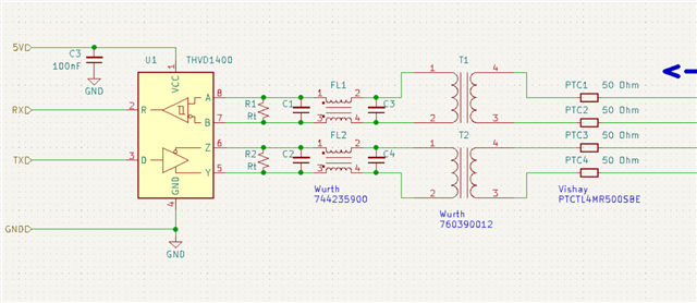
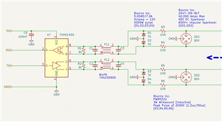
Here is the schematic:

  • Hi Seth,

    So it really depends - we have one application note that uses a transformer for a high voltage interface (https://www.ti.com.cn/cn/lit/an/slla590/slla590.pdf?ts=1674486505737) but we have an additional high speed line driver to drive a low impedance load. 

    There are a few concerns with putting a transformer on the line in general applications:

    1. The transformer adds an inductive load which will cause impedance mismatches when looking at standard RS-485 implementation (120 Ohm twisted pair and 2 termination resistors on the bus, one at each end equal to 120 Ohms to prevent reflections. Leakage inductance from the transformer will also add attenuation to the total system. In this application the impedance matching isn't as important as the bus is short compared to wavelength of the signal so you should mostly be able to assume a lumped circuit model for the design. But there could be some distortion due to the LRC components on the line.

    2. Besides the potential attenuation the other issue is the impedance as viewed from the driver. The transformer will have an inductance value (the one you have listed is 475uH I believe) This loads the driver - if the TX and RX have differential terminations- so does the transformer and at 475uH at max data rate (500kbps ~250KHz) is ~120 Ohms - with the transformers and termination resistors the impedance needs to be >54 ohms - in this system it doesn't seem to meet the requirement. If that is the case than an additional line driver (we have used the THS6222 in the past) can be used to drive the load.

    3. Since the max data rate is lower for this device (500Kbps) there is a possibility that average signal or in cases of consecutive logic highs (or lows) that the transformer core could potentially saturate and cause major EMC / EMI issues or damage the transformer. For lower data rates it may be beneficial to add encoding schemes to remove as much of the "DC" level as possible from the data-signal - this may limit bandwidth - or verify the transformer will not saturate under the run time conditions - I can't really tell from the transformer datasheet how much of a concern this may be in the application.

    I do also have a few notes on the  application itself.

    1. While we don't have reference material on the specific protection you are seeking there is one thing that we usually recommend in any protection scenario which is protection diodes from B to GND and from A to GND on every node to help shunt any excess current that was attenuated elsewhere in the circuit as the THVD1400 needs to keep the voltages at A or B to its GND between +/-16V to prevent damage. All the other protection that you added (common mode choke and filter caps) are common so I don't see an issue there.

    2. Along with the protection diodes series pulse proof resistors ~10 to 100 ohms (on A and B for every node before the termination resistor) also is suggested for surge transients. 

    3. The 50 Ohm resistors on the isolate bus are a bit concerning as the transformer isn't going to be stepping up/down that much so that additional 100 Ohms on the line will probably kill the communication unless the voltage is boosted by an additional line driver to drive a large current (if these resistors are there for matching reasons - which I am assuming they are - but please correct me if I am mistaken) 

    4. Finally I do want to suggest the THVD2410 - its essentially very similar to this device but has a +/-70V fault rating - which can help add a layer of protection to the system. We also do have a few surge rated devices - not the surge from a lighting bolt - but integrated surge diodes would most likely be beneficial in the system - so if you have reasons for picking 1400 please let me know as I think we may have better devices for these types of applications (important things of note are voltage supply and data rate - if there is a specific need).

    Please let me know if you have any other questions and I will see what I can do!

    Best,

    Parker Dodson

  • Parker,

    Thanks for this timely and thorough response. I have taken all of your advice into consideration and completely redesigned the protection circuit.

    Here is what I came up with:

    I think the THVD2410 would be a great substitute for the THVD1400, especially since it is a pin-for-pin replacement. Unfortunately there is no stock of this part and so I am trying to select parts that have reliable stock.

    I'm ditching the isolation transformers and replaced them with two voltage clamping elements: a TVS that clamps to 12V and a GDT that clamps to 12V but allows an impulse of 650V+. Between these elements is a pulse-proof resistor.

    I'm a little bit concerned with the inductance of the pulse-proof resistors and the capacitance of the TVS diodes. These values are not given in the datasheets and so it's hard for me to quantify the effect they might have on the THVD1400 communication. There are non-inductive versions of the pulse-proof resistors but they aren't in stock. Might have to order them anyway and eat the long delivery time.

  • Hi Seth,

    I understand the changes that you have made.

    One question:

    1. What value are you planning on terminating the bus with ? 

    My main concern is communication - with the current setup the driver will see ~97 Ohm (assuming standard term value of 120 Ohms)  of impedance between A and B (which is fine) - the issue comes down to what the receiver will see. 97 Ohms is pretty close to our spec for RS-422 VOD (which uses a 100 Ohm load) with a typical of 2.5V and a min of 2V - if this is the case under minimum conditions the receiver will be at ~|430mV| - which it can receive but the margin is much lower than before. If you are not using 120 Ohms as the termination resistor then this may not be as much of a problem. At the max data rate of the device you can neglect transmission line effects for the fundamental, second, and third harmonics for a bus length of 50 feet (you really don't need to be concerned up to 60m and 50 ft ~15 meters so 4th harmonic is where you may start seeing some reflections  - so a small portion of the energy may still be able to reflect in non-impedance matched systems. This means you may not need the termination in this system and remove the issue of bus attenuation. 

    Typically we also suggest the pulse proof resistors are placed before TVS diode (in between THVD1400 and TVS diode) to help protect the inputs of the transceiver - this may not be as necessary in this system due to the filtering after the TVS diode, but I did want to point that out just as a note.

    I would try to minimize the inductance - and generally I would recommend the non-inductive wire-wound resistors in this application - usually we suggest thick film - but due to the application I would lean towards the non-inductive wire wound. I am not as concerned with the TVS diode capacitance as the cable usually will have much more capacitance than a TVS diode - there are edge cases - but generally we usually don't see capacitance issues with TVS diodes in point to point applications with a short bus. 

    Please let me know.

    Best,

    Parker Dodson

  • The characteristic impedance of the transmission wires is 99 Ohm so I was planning on using that for the termination resistor value to reduce reflections. However, I didn't consider that reflections are a non-issue considering the wavelength and relatively short wires. I might even reduce baud rate to 100 kbps. I will remove the termination resistors.

    I think I understand how you arrived at ~97 Ohms if you treat the resistor network (with Rt = 120) as a Thevenin equivalent (with VOD of 2V between A and B). But if you remove the termination resistors, the A and B lines are separated, so, how would I calculate equivalent resistance (from the driver's perspective) in that situation? Is the input impedance of the receiver known? I noticed Figure 6-1 for the THVD1400 datasheet uses 375 Ohm resistors for this. If I use this value then I calculate an equivalent resistance of 1150 Ohm (across driver A and B), current of 1.74 mA, and a voltage of 1.3V across the receiver. Not sure if this is right or not...

    I can reduce the resistance of the wire-wound resistors but then they will be subject to a higher current pulse. I would have to double-up the resistors to share the pulse. This isn't preferable but I'll do it if needed to in order to maintain reliable communication.

    I'll make sure to get the non-inductive versions of resistors.

    I'll add 10 Ohm thick-film resistors at the inputs of the transceiver. They shouldn't need to be as heavy-duty as the 100 Ohm wire-wound resistors.

    I think we got a workable solution here. Just to summarize, the changes I'll be making will be the following:

    • remove termination resistors
    • add 10-Ohm pulse proof resistors to transceiver input terminals
    • make sure to use non-inductive resistors

    Let me know if I misunderstood any of your statements or if I made errors in my calculations above. Thanks for your feedback.

  • Hi Seth,

    So if the termination is removed the driver is essentially being fed into a high impedance load - which is why the short bus/slow data rate is important if the termination is removed because energy that could be reflected is small - but there will most likely be some higher order reflections still. The input impedance of the receiver is "known' but not explicitly stated.

    1. The quick way to calculate is to use the number of nodes supported (256 for this device) and multiple by 375 as that is the standard impedance for a 1/8th unit load device (96K)

    2. A more accurate view point is to take the input bus current and divide by input voltage as stated in datasheet and use a linear regression to approximate the typical and worst case scenarios as over operation range the input current change is pretty linear. 

    So for this device typically the bus input current at -7V is -70uA  (100K) and 12V is 75uA (160K) and worst case -7V is -97uA (~72K)  and 12V is 100uA (120K)

    Since the resistance varies with voltage its very hard to impedance match - the short bus/remove terminations resistor scenario is for system that won't have a lot of energy prone to reflecting, which at 100kbps the energy that would be in the harmonics that would be reflected is negligible. Essentially at that slow speed the reflections are going to be from the rise time/fall time of the differential signal  - which also shouldn't be that large of an impact because this device is generally slower already - so I don't anticipate much reflection in the system (but there will probably be a little - but I doubt it should hinder communication)

    Yes - you got all the recommended changes that I think should be important in the design and I think we are aligned - please let me know if you have any other questions and I will see what I can do.

    Best,

    Parker Dodson

  • Great! Again, really appreciate the help. This is why I prefer TI products ^^