Part Number: TL28L92
Hi everyone,
We switched from NXP SC28L91 to TL28L92 due to obsolescence of the former. We are surprisingly facing several issues, the TL28L92 is supposed to be compatible - except the second channel.
The following described functions are working properly with the SC28L91. The hardware – our PCB – did not change, we just replaced the UART and disconnected the pin 5.
We only use the channel A.
Code
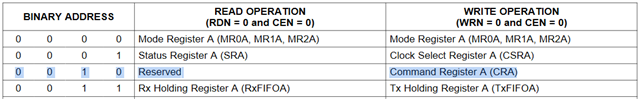
CRA = 0xB0; // Pointer to MR0A.MR0A = 0x38; // FIFO 16 bytes, TxINT = 1 or more bytes empty, RxINT = 1 or more bytes in FIFO. MR1A = 0x13; // 8 data bits, no parity, RxINT = 1 or more bytes in FIFO.MR2A = 0x27; // 1 stop bit, RTS controlled by the transmitter.ACR = 0x10; // Counter mode with 1x clock of channel A transmitter.CSRA = 0x66; // 1200 bauds.CTPU = 0x00; CTPL = 0x0A; // 1.125 time of a character.CRA = 0xA1; // Enable receiver and set time-out mode on.IMR = 0x11; // TxA interrupt, RxA interrupt, Counter ready.
1. Time-out mode
We use the time-out mode to automatically start/stop the counter upon the received data stream. See below how we proceed:
Observation: the interrupt pin goes down upon reception of a character but it never goes down at the end of the frame. It seems that the time-out mode does not work.
If we set the counter mode with clock (X1/CLK) divided by 16, the time-out mode works correctly. Why?
2. TxA interrupt
Observation: the UART interrupts when the transmitter is enabled. We load TxFIFOA with the first byte but then, the UART never attempts to interrupt again. The interrupt pin stays active (low level). It interrupts when 16 bytes are sent.
Solution: we set MR0A[5:4] to 0b00. Then, the UART interrupts for each character.
It seems that the table 3-23 in the datasheet is not correct. TxEMPTY and TxRDY conditions are swapped.
3. RTS via the output OP0
MR2A = 0x27; // 1 stop bit, RTS controlled by the transmitter.CRA = 0x84; // Enable transmitter and assert RTSN.
We send a message.
Observation : the output OP0 stays at high level, it never goes down. Why?
We found out a solution to fix issues 1 and 2 but we are stuck on the third one.
What do you think?
Thank you in advance for your help.
Regards,