Because of the holidays, TI E2E™ design support forum responses will be delayed from Dec. 25 through Jan. 2. Thank you for your patience.

This thread has been locked.

If you have a related question, please click the "Ask a related question" button in the top right corner. The newly created question will be automatically linked to this question.

DS160PT801X16EVM: I can't see proper retimer(DS160PT801X16EVM) Gen3 performance with Gen3 NVMe.

Part Number: DS160PT801X16EVM
Other Parts Discussed in Thread: DS160PT801

Previous E2E Case : https://e2e.ti.com/support/interface-group/interface/f/interface-forum/1189931/ds160pt801x16evm-ds160pt801x16evm

Before read below my quesetion, Please read "Previous E2E Case" First.

It may help you understand my qeustion.

========================================================================

Part of Previous E2E Case

I can't see proper retimer(DS160PT801X16EVM) Gen3 performance with Gen3 NVMe.
Please check my test results and then give me feedback. 

1. Test Environment
1) ubuntu PC : Intel(R) Core(TM) i9-10900 CPU, 64GB Memory PC
2) ubuntu Version : Ubuntu 18.04.6 LTS
3) Retimer : DS160PT801X16EVM
4) NVMe : Micron MVMe Gen3 x4. 21100AT M.2 SSD

2. My Three Test Cases
1) Direct NVMe connection through PCIe Slot : Main board <-> PCIe to M.2 convert board <-> NVMe
   NVMe is normally recognized as PCIe Gen3(ASPM Disabled) and Good Stable performance

2) Use TI Retimer : Main board <-> TI retimer(DS160PT801X16EVM) <-> PCIe to M.2 convert board <-> NVMe
   NVMe is normally recognized as PCIe Gen3(ASPM L1 Enabled) and But Unstable performance

3) Use TI Retimer(Force Gen2 in BIOS Setting) : Main board <-> TI retimer(DS160PT801X16EVM) <-> PCIe to M.2 convert board <-> NVMe
   NVMe is recognized as PCIe Gen2 and Stable performance

========================================================================

<< My Question >>

I found "PCIe Signal Integrity Challenges and Remedies" TI's doc.

In this doc. there are PCIe specification by generation.

gen3 needs HEO <= 0.3 UI and VEO <= 25mV
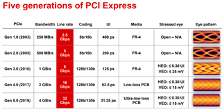
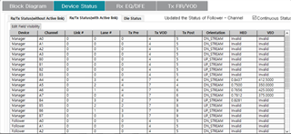
So. I checked HEO and VEO using SigCon Architect program.

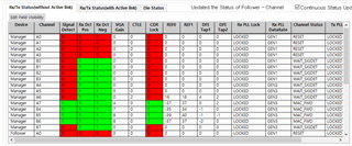
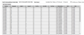
I think HEO and VEO are higher than spec.

please review it.
Finally To improve the Gen3 throughput, What more should I check?

thanks,

hochang.

  • Hello hochang,

    In the slides you show.  The HEO <= 0.3UI and VEO <= 25mV values represent the HEO and VEO for a Stressed Eye Diagram for each PCIe generation.  It is meant to show that a PCIe receiver should be able to recover a stable signal even under these poor conditions.  

    The HEO and VEO values that are shown in SigCon Architect represent the HEO/VEO inside the retimer after some signal conditioning is applied.  It should be greater than 0.3UI and 25mV.  The higher the better!

    Do you want to improve the Gen3 throughput for this test condition?

    1) Direct NVMe connection through PCIe Slot : Main board <-> PCIe to M.2 convert board <-> NVMe
       NVMe is normally recognized as PCIe Gen3(ASPM Disabled) and Good Stable performance

    ...or for this test condition?

    2) Use TI Retimer : Main board <-> TI retimer(DS160PT801X16EVM) <-> PCIe to M.2 convert board <-> NVMe
       NVMe is normally recognized as PCIe Gen3(ASPM L1 Enabled) and But Unstable performance

    To improve the throughput for test case #1, there first must be bit errors occurring between the retimer and the CPU or the retimer and the NMVe.  If there are no errors, then there is nothing that can be done because the PCIe link is already working as best as possible.

    If there are bit errors, then throughput could be improved by reducing the Bit Error Rate (BER) of the PCIe link between the CPU and retimer or the PCIe link between the retimer and NVMe.  We would need to do some debug to count the number of errors and see if anything can be done to reduce them.

    test case #2 sounds more like a system issue that we would need to investigated and resolved so that it has stable performance before trying to improve the throughput.

    Regards,

    Nicholaus

  • The HEO <= 0.3UI and VEO <= 25mV values represent the HEO and VEO for a Stressed Eye Diagram for each PCIe generation

    Dear Nicholaus,

    Thanks for update.

    I would like to investigate test case #2 further.

    Test case #1 does not use retimer. So don't care.

    To improve test case #2, what should I check more?

    If you share check list to me, I will try to that.

    thanks,

    hochang.

  • Hi Hochang,

    Please allow Nicholaus and I some time to review this problem and get back to you.

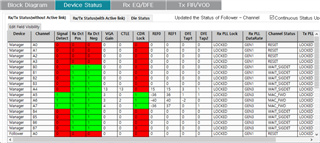
    It seems that the retimer is not detecting a signal on all 4 PCIe lanes (A4-A7, B4-B7) when the M.2 is connected. Is this the case when using both EEPROM images (4x4 and 'DS160PT801.hex')?

    The eye opening on channels A4-A7 appears fine. As Nicholaus stated, a larger eye opening is better.

    Best,

    David

  • Dear David,

    Please allow Nicholaus and I some time to review this problem and get back to you.

    => Ok, I will wait for your feedback.

    It seems that the retimer is not detecting a signal on all 4 PCIe lanes (A4-A7, B4-B7) when the M.2 is connected. Is this the case when using both EEPROM images (4x4 and 'DS160PT801.hex')?

    => Yes, Same result when I try to two EEPROM Image(4x4 and 'DS160PT801.hex')

    The eye opening on channels A4-A7 appears fine. As Nicholaus stated, a larger eye opening is better.

    => Ok, thanks

  • Hi Haochang,

    Sorry, I didn't realize that test case #1 wasn't using a retimer.

    For the retimer test case (Test Case #2), have you tried the same test with L1 disabled?  As David said, the interesting thing in the data you sent is that B4-B7 isn't detecting a signal.   I'm wondering if the PCIe link is in the L1 state.

    Regards,

    Nicholaus

  • Hi Hochang,

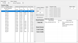
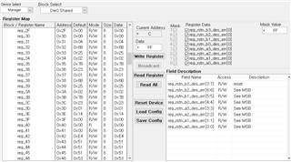
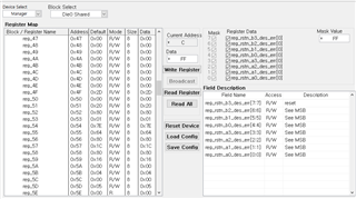
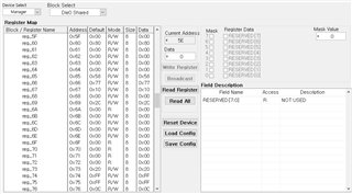
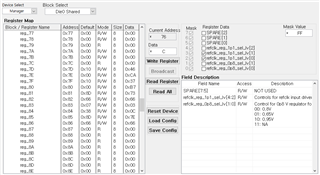
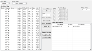
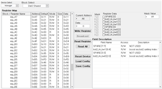
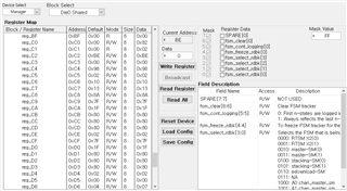
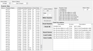
    I'd like to verify one thing right now. Could you check what the register value of Global Register 0xF1 is using the Low Level Page of the GUI?

    -David

  • Dear Nicholaus and David,

    I'm sorry for late reply.

    1. David's Question

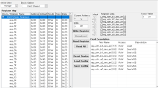
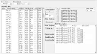
    I'd like to verify one thing right now. Could you check what the register value of Global Register 0xF1 is using the Low Level Page of the GUI?

    1) Global

    2) Die 0 Shared

    2. Nicholaus's Question

    For the retimer test case (Test Case #2), have you tried the same test with L1 disabled? 

    => Yes, Same bios settings(disable PCIe ASPM)

    As David said, the interesting thing in the data you sent is that B4-B7 isn't detecting a signal.   I'm wondering if the PCIe link is in the L1 state.

  • I found the python API tool provided by TI.

    And I used this tool, I can get RTSM. Please review it.

    -- Main Menu --
    0. Exit
    1. Read Retimer Channel Status
    2. Read Retimer Status
    3. Read State Machine Trace
    4. Set State Machine Trace
    5. Set Loopback Mode
    6. Create/Save an Eye Diagram
    7. Read Register
    8. Read/Write EEPROM
    9. Compliance & Eval

    Please select an option: 3
    +----------++------++------------++----------------++------------------------++----------------------+
    | Address || Die || Pckg Lanes || Mode || State Machine Type || Trace |
    +----------++------++------------++----------------++------------------------++----------------------+
    | 0x20 || 0 || Lanes 4-7 || First N-States || RTSM X2(0): Main RTSM || 15. DETECT_TS1_TS2 |
    | || || || || || 14. FORWARD |
    | || || || || || 13. EIOSQ_TRAINING |
    | || || || || || 12. ELEC_IDLE_TRNG |
    | || || || || || 11. DETECT_TS1_TS2 |
    | || || || || || 10. FORWARD |
    | || || || || || 9. EIOSQ_TRAINING |
    | || || || || || 8. ELEC_IDLE_TRNG |
    | || || || || || 7. DETECT_TS1_TS2 |
    | || || || || || 6. FORWARD |
    | || || || || || 5. EIOSQ_TRAINING |
    | || || || || || 4. ELEC_IDLE_TRNG |
    | || || || || || 3. DETECT_TS1_TS2 |
    | || || || || || 2. FORWARD |
    | || || || || || 1. EIOSQ_TRAINING |
    | || || || || || 0. ELEC_IDLE_TRNG |
    +----------++------++------------++----------------++------------------------++----------------------+
    | 0x20 || 1 || Lanes 0-3 || First N-States || RTSM X2(0): Main RTSM || -- Trace is empty -- |
    +----------++------++------------++----------------++------------------------++----------------------+
    | 0x22 || 0 || Lanes 4-7 || First N-States || RTSM X2(0): Main RTSM || -- Trace is empty -- |
    +----------++------++------------++----------------++------------------------++----------------------+
    | 0x22 || 1 || Lanes 0-3 || First N-States || RTSM X2(0): Main RTSM || -- Trace is empty -- |
    +----------++------++------------++----------------++------------------------++----------------------+

    Ubuntu PC hdparm test result

    bsppower@bsppower-ThinkCentre-M90t:~$ while true; do sudo hdparm -t /dev/nvme0n1;sleep 1;done

    /dev/nvme0n1:
    Timing buffered disk reads: 182 MB in 3.01 seconds = 60.55 MB/sec

    /dev/nvme0n1:
    Timing buffered disk reads: 82 MB in 3.07 seconds = 26.67 MB/sec

    /dev/nvme0n1:
    Timing buffered disk reads: 188 MB in 3.01 seconds = 62.39 MB/sec

    /dev/nvme0n1:
    Timing buffered disk reads: 88 MB in 3.00 seconds = 29.30 MB/sec

    /dev/nvme0n1:
    Timing buffered disk reads: 90 MB in 3.02 seconds = 29.79 MB/sec

    /dev/nvme0n1:
    Timing buffered disk reads: 100 MB in 3.01 seconds = 33.24 MB/sec

  • Hi Hochang,

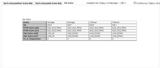
    Your nvme test, while true; do sudo hdparm -t /dev/nvme0n1;sleep 1;done, looks like it's successfully receiving data, but the digital status of the retimer indicates the PCIe link is failing.  This doesn't make sense to me.  If the link is failing there should be no data going to the nvme drive.

    What clocking topology is used in this design?  Is it common clock, independent clock, or SSC?

    Regards,

    Nicholaus

  • Hi Hochang,

    Have there been any updates on this issue?

    Thanks,

    Nicholaus

  • Dear Nicholaus,

    Thanks for support.

    After change NVMe from Micron to Samsung. the problem disappeared.

    I will close this case and open a new case if another problem arises.

    Thanks,

    hochang.