This thread has been locked.

If you have a related question, please click the "Ask a related question" button in the top right corner. The newly created question will be automatically linked to this question.

DP83867IS: No response on MDIO lines

Part Number: DP83867IS

Hi,

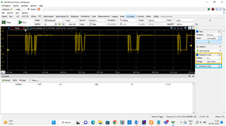
When I read the PHY ID through the mdio interface, one of my PHY devices did not return a valid ID. Clock input is 25MHz. Clock out is also 25MHz. All the voltages are properly fed to the IC.

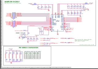
Strap values are correct. There is no resposne from IC on MDIO lines. Please help

Regards,

SCH

  • Hi Shradha,

    Can you clarify what you mean by PHY ID? Do you mean PHY Address (set by straps). Or register 0x3 is not returning 0xA231?

    If the former, can you show me how you are checking the PHY address? Are you guessing and checking addresses 0x0 - 0xF? If the latter, are other registers able to be read?

    Thanks,

    David

  • Hi David,

    Thank you for replying. Problem is  register 0x3 is not returning 0xA231. Yes i am checking all the 15 addresses from 0 to 0xF. I did not try to read other register.

    I am providing 25MHz clock to clock input and I can see the clock in clkout pin (#18 pin)

    Regards,

    Shradha

  • Hi,

    I tried reading from below registers.

    1. PHY Identifier Register #1 (PHYIDR1) with Address 0x0002 and 

    2. . Auto-Negotiation Advertisement Register (ANAR), Address 0x0004 

    Even these registers read 0XFFFF like register 0x3. 

    Below is the image of the MDIO data lines.

    As per the protocol, in the above waveform,

    2 bits start bit,

    2 bits read,

    5 bits PHY address,

    5 bit reg address

    are there.

    But after that i was suppose to get 16 bit data which is not there in the waveform.

    Regards,

    SCH

  • Hi Shradha,

    You mentioned "one of my PHY devices". How many PHYs are functioning correctly? Are they all on the same MDIO bus? What is different between a functioning and non-functioning PHY? 

    Please share the schematic if you can.

    Thanks,

    David

  • Hi,

    Yes. I have 7 boards in which this communication is perfectly fine in 3 boards. In other boards i am facing issue. All the boards are same in all aspects.(SCH, FAB and BOM.)

    Schematic:

    Regards,

    SCH

  • Hi Shradha,

    Need your help to figure out if anything is different between the good and bad boards. Is everything about the setup, measurement, programming method exactly the same? All the PHY address straps are identical on each board?

    To check the health of the PHYs, can you probe the CLKOUT, RXCLK, and then the MDI pins. Compare these signals on a good board vs bad board, do they look any different?

    Can you share a higher quality version of the schematic? I cannot read some of the signal names.

    Thanks,

    David

  • Hi David,

    As I mentioned, all the boards are same and I am getting CLKOUT properly. One thing I missed to tell you is that I have option for 3 DP83867 on my board. My board has 3 ethernet ports. But only one IC is powered on and among other 2 PHY ic s, one is placed (Lets consider it as PHY-2) but is NOT powered on.

    The MDIO lines were shared between PHY-1 and PHY-2. I separated the MDIO connections between PHY 1 and  PHY2 because of which PHY-1 IC responded with expected 0xA231. PHY-1 IC is working.

    I powered PHY-2 on, but it is not responding . Schematic wise, both sections are same. I have connected separate MDIO lines from Processor to PHY-2 (MDIO lines are different for PHY-1 and PHY-2 ). Also I am getting CLKOUT on this IC. There is data from processor to PHY-2 on MDIO lines like it was happening in PHY-1.  I have compared the signals from working and non working PHY. PHY-2 response is not there in the waveform. I tried to read 0XA231 from the register. (Trying with same code as in PHY-1). 

    I have also tried with same and different PHY addresses ( tried by making strapping pins same as PHY-1).

    Is there any special requirement to be taken care of, while using 2 PHY ics?

    Also, why PHY-1 was not responding on MDIO lines, when same MDIO lines were connected to another PHY which was turned OFF (No power was given).? ( I think Multiple slaves could be connected to MDIO lines)

    Thank you in advance

    Regards,

    Shradha

  • Hi,

    I compared PHY-2 and PHY-1 pins in On condition. RBIAS pin in working IC is HIGH where as it is in PHY-2 is 0V. Can you please tell me the significance of it?

    Regards,

    Shradha

  • Hi,

    I compared PHY-2 and PHY-1 pins in On condition. RBIAS pin in working IC is HIGH where as it is in PHY-2 is 0V. Can you please tell me the significance of it?

    Regards,

    Shradha

  • I can read reg 2 of PHY-2 (value: 0x2000) but not reg 3 (Value: 0xa231)

  • I can read reg 2 of PHY-2 (value: 0x2000) but not reg 3 (Value: 0xa231)

  • Hi Shradha,

    If there is no voltage on the RBIAS pin, the device is not powered up correctly. Please make sure the power rails are all supplied with the expected voltage. Is the failure seen in the same port on each board? Please share a high quality schematic that I can check.

    Thanks,

    David 

  • Hi David,

    supply voltages donot varry more than 1% from specified value. Is it possible to read second reg correctly, not the third one? Also second reg reading is not consistent. Sometimes it reads 0x2000 but most of the times 0xffff.

    Attaching the sch

    6153.dp83867.pdf

    Thanks,

    Shradha

  • Hi David,

    I made few changes in dts file and kernal. Now PHY-2 is also working. I am getting HIGH at RBIAS pin aswell. Thank you very much for your support.

    Gratefully,

    Shradha C H