This thread has been locked.

If you have a related question, please click the "Ask a related question" button in the top right corner. The newly created question will be automatically linked to this question.

DS90UB954-Q1: CSI Replicate Mode mipi error

Part Number: DS90UB954-Q1


Hello Team:

Below is the block diagram of my system.

sensor A:  2 Lanes, 445.5Mbps/Lane,  1920 x 1080@30fps.  VC-ID: 0

sensor B:  2 Lanes, 445.5Mbps/Lane,  1920 x 1080@30fps.  VC-ID: 1

953: 4 Lanes, 800Mbps/Lane

954: 2 Lanes, 1.6Gbps/Lane

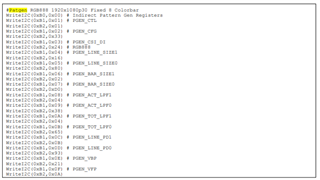
I used below Initialize sequence. 

  // init 954
  {UB954,0x32,0x01},
  {UB954,0x4c,0x01}, // rx0
  {UB954,0x65,0x18}, // sensor A
  {UB954,0x72,0xe4}, // sensor A vc0 remap vc-0
  {UB954,0x4c,0x12}, // rx1
  {UB954,0x65,0x20}, // sensor B
  {UB954,0x72,0xe1}, // sensor B vc1 remap vc-0
  
  {UB954,0x4c,0x03}, // rx0 & rx1
  {UB954,0x58,0x5a}, // 0x5a:10 Mbps (non-synchronous)
  {UB954,0x5c,0x30}, 
  {UB954,0x5d,0x34},
  {UB954,0x6d,0x7C},
  {UB954,0x7C,0x00},
  {UB954,0xB9,0x3F},
  /////// wait for stable LCOK /////////
  // init 953
  {UB953,0x01,0x01,0x0}
  {UB953,0x33,0x00,0x0}, 
  {UB953,0x02,0x73,0x0}, //4 lane continous clk
  {UB953,0x05,0x00,0x0}, 
  {UB953,0x06,0x49,0x0},
  {UB953,0x07,0xF2,0x0}
  
  // enable csi & forwarding.
  {UB954,0x33,0x21,0x00}, // enable csi & 2 lane.
  {UB954,0x21,0x81,0x00}  // CSI Replicate Mode & Round robin forwarding.

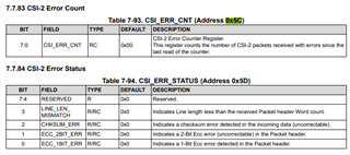
is my initialization code is ok? Virtual ID assignment is OK?  But the ISP's Mipi report error as following.

[  216.708758] CAM_ERR: CAM-ISP: cam_ife_csid_irq: 5137 CSID:1 UNBOUNDED_FRAME: Frame started with EOF or No EOF
[  216.708766] CAM_ERR: CAM-ISP: cam_vfe_bus_error_irq_top_half: 2651 Bus Err IRQ
[  216.708778] CAM_ERR: CAM-ISP: cam_vfe_bus_error_irq_top_half: 2655 vfe:1: IRQ_Status0: 0x4000
[  216.708783] CAM_INFO: CAM-ISP: cam_ife_csid_irq: 5145 CSID: 1 Error IRQ Count:1
[  216.708790] CAM_ERR: CAM-ISP: cam_vfe_bus_error_irq_top_half: 2655 vfe:1: IRQ_Status1: 0x0
[  216.708795] CAM_INFO: CAM-ISP: cam_ife_csid_irq: 5305 CSID:1 IPP_PATH_ERROR_CCIF_VIOLATION: Bad frame timings
[  216.708802] CAM_ERR: CAM-ISP: cam_vfe_bus_error_irq_top_half: 2655 vfe:1: IRQ_Status2: 0x0
[  216.708806] CAM_INFO: CAM-ISP: cam_ife_csid_irq: 5469 CSID:1 RDI :1 PATH_ERROR_CCIF_VIOLATION: Bad frame timings
[  216.708865] CAM_ERR: CAM-ISP: cam_ife_csid_irq: 5137 CSID:2 UNBOUNDED_FRAME: Frame started with EOF or No EOF
[  216.708872] CAM_INFO: CAM-ISP: cam_ife_csid_irq: 5145 CSID: 2 Error IRQ Count:7
[  216.708877] CAM_ERR: CAM-ISP: cam_vfe_bus_err_bottom_half: 1460 Bus Violation: debug_status_0 = 0x2
[  216.708890] CAM_INFO: CAM-ISP: cam_vfe_bus_err_bottom_half: 1466 RDI 1 violation
[  216.708925] CAM_ERR: CAM-ISP: __cam_isp_ctx_handle_error: 2488 Error with no active/wait request
[  216.709009] CAM_WARN: CAM-ISP: __cam_isp_ctx_handle_error: 2643 Notify CRM: req 0, frame 1 ctx 0, error 2

I would like to enquire what‘s reason caused the mipi error? 

Thanks & Regards,

Willywan.

  • Hi Willywan,

    Thank you for your enquiry. I am reviewing the information you provided and will provide feedback within 2 days. 

    Glenn  

  • I Willywan,

    I reviewed your code and I believe you didn't enable the CSI forwarding (0x20).

    Please see attachment with my comments in red. 

    Init_Review.xlsx

    Glenn 

  • Hello Glenn,

    I corrected the registers config. as following attachment. But CSI report error too. 

    Init_correct.xlsx

    When I opening Sensor A and saw the previews,  then I open Sensor B, the CSI report errors. Does the 954's csi replicate mode support this scenario of controlling the camera separately?

    sometimes csi reported follow errors and so on.

    CAM_ERR: CAM-ISP: cam_ife_csid_irq: 5085 CSID:2 ERROR_CRC CPHY: Long pkt payload CRC mismatch
    CAM_INFO: CAM-ISP: cam_ife_csid_irq: 5145 CSID: 2 Error IRQ Count:1
    CAM_ERR: CAM-ISP: cam_vfe_bus_error_irq_top_half: 2651 Bus Err IRQ
    CAM_ERR: CAM-ISP: cam_vfe_bus_error_irq_top_half: 2655 vfe:2: IRQ_Status0: 0x4000
    CAM_ERR: CAM-ISP: cam_ife_csid_irq: 5137 CSID:2 UNBOUNDED_FRAME: Frame started with EOF or No EOF
    CAM_ERR: CAM-ISP: cam_vfe_bus_error_irq_top_half: 2655 vfe:2: IRQ_Status1: 0x0
    CAM_ERR: CAM-ISP: cam_vfe_bus_error_irq_top_half: 2655 vfe:2: IRQ_Status2: 0x0
    CAM_INFO: CAM-ISP: cam_ife_csid_irq: 5145 CSID: 2 Error IRQ Count:4
    CAM_INFO: CAM-ISP: cam_ife_csid_irq: 5305 CSID:2 IPP_PATH_ERROR_CCIF_VIOLATION: Bad frame timings
    CAM_INFO: CAM-ISP: cam_ife_csid_irq: 5469 CSID:2 RDI :1 PATH_ERROR_CCIF_VIOLATION: Bad frame timings
    CAM_ERR: CAM-ISP: cam_vfe_bus_err_bottom_half: 1460 Bus Violation: debug_status_0 = 0x2

  • Hi Willywan,

    Let me deep dive into your code one more time.

    Please allow two working days.

    Glenn 

  • Hello Glenn,

    I read the state registers as follows:

     rx0: 0x4d = 0x03, 0x4e = 0xc (or 0x4e = 0xcd),

     rx1: 0x4d = 0x43, 0x4e = 0x4,

     as the datasheet of 954, the FREQ_STABLE has set 1, why ?  

  • Hi Willywan,

     as the datasheet of 954, the FREQ_STABLE has set 1, why ?  

    This indicating that the clock is stable on both cameras. Have you tried swapping the cameras?

    Glenn 

  • Hello Glenn,

    I swapping cameras many times  but it also reported same mipi errors . the rx ports lock & pass is stable, clock is stable too, our 954 and 953’s registers config is correct ?

  • HI Willywan,

    Thanks for your patience, everything so far looks fine from the script side. 

    I have some ideas to try. 

    1. Can you please read register 0x4E on each port? Want to see what errors the 954 is detecting.
      1.  A full register dump will also be appreciated including both ports. 
    2. You setup 953 in continuous but does your ISP need continuous or non-continuous?
    3. Can you complete the following information? This might be a bandwidth limitation.
    Port Number Horizontal Active Pixels Vertical Active Lines* Vertical Total Lines (sensor Vendor) Frame Rate (Hz) Bits Per Pixel Imager Per Lane MIPI Speed (Mbps/lane)
    0 2560 1984 4244 30 10  
    1 3840 2167 2300 30 12  
    Number of Sensors 2
    RX Ports  RX0 + RX1
    Clock Type Continuous Clock
    CSI-2 Lane Speed 1.6Gbps
    CSI-2 Lanes 4
    Forwarding Mode Best Effort Round Robin

    Glenn  

  • Hello Glenn,

    Thank you for you reply.

    • Can you please read register 0x4E on each port? Want to see what errors the 954 is detecting.
      1.  A full register dump will also be appreciated including both ports. 
    • You setup 953 in continuous but does your ISP need continuous or non-continuous?
    • Can you complete the following information? This might be a bandwidth limitation.

    1,I changed the register to non continuous clock (0x02=0x33) on 953., so 953, 954 and ISP all are non continuous clock.

    2,   I read register status for both ports.  rx0: 0x4e = c5, rx1: 0x4e = c5,and I add info.xslx  as following attachment, pls review. 

    info&dump.xlsx

    3,note: when I open sensor B, the sensor A is enabled.

    Thanks,

    Willywan

  • Hi Willywan,

    Here are more things to try as looking through the logs there seems to be line length changes. Also, in the register dump you provided register 0x4E is set 0x4 which means there is no errors. You indicated that you read 0x4E to be 0xC5 on your message. Do you know why the log is contradicting this?

    1. Try Enabling sensor B and disable A Camera
      1. want to determine if you have errors with just this camera 
    2. Switch cable A with B

    please keep the same hardware in each port except for the swap of the cables. 

    Glenn 

  • Hello Glenn,

    Here are more things to try as looking through the logs there seems to be line length changes. Also, in the register dump you provided register 0x4E is set 0x4 which means there is no errors. You indicated that you read 0x4E to be 0xC5 on your message. Do you know why the log is contradicting this?

    sorry, I read the register 0x4e only (don't read others registers) before dump all registers.  I suspect it should be the this.

  • Hello Glenn,

    • Try Enabling sensor B and disable A Camera
      1. want to determine if you have errors with just this camera 
    • Switch cable A with B

    if enabing sensor B and disable A Camera, that can be working  properly. and switch A with B , they working properly with single enable each sensor too.

  • Hi Willywan,

    That is good to know that it works with sensor B with sensor A disabled. 

    The best course of action is to go step by step till we find what is happening. Can we try doing this without duplicate mode? See if we have both sensors on without replicate mode you don't get errors. This will let's know where to focus on the debug. 

    Glenn 

  • Hello Glenn,

    The best course of action is to go step by step till we find what is happening. Can we try doing this without duplicate mode? See if we have both sensors on without replicate mode you don't get errors. This will let's know where to focus on the debug

    The both sensors can works well only when both sensors are enabled at the same time without replicate. But it can‘t works when enable each sensor seperatly at the different time without replicate. then, csi reports long package ERROR CRC.

  • Willyman,

    What about both turning on both sensors at the same time and replicate mode? 

    Glenn 

  • Hello Glenn,

    What about both turning on both sensors at the same time and replicate mode?

    turning on both sensors at the same time with replicate mode, which the csi also report same errors,crc error, lanex_fifo_overflow,  ipp path error ccif violation, unbounded frame and so on. when I enabled both camera, what's more, the csi will also report errors during long time previews, then, camera stop works.

  • HI Willywan,

    In the scenario where you are running both camera without replicate mode. It seems to be working but eventually fails. Can you look at register 0x4E on each port? We should see some errors happening on the 954.

    Glenn 

  • Hello Glenn,

    In the scenario where you are running both camera without replicate mode. It seems to be working but eventually fails. Can you look at register 0x4E on each port? We should see some errors happening on the 954.

    the 0x4e = 0xc5 on each port, which means the line length and line count unstable ?  how do I troubleshoot it ?

  • Hi Willywan,

    You will need to look at your 953 and read the registers below. This will tell us if there is any issues on the incoming data. 

    If there is a mismatch, then we can try to enable the internal patgen on each 953 to 954 to test the data path.  Please see section 7.6 Pattern Generation for configuration. When using the patgen you will not turn on the sensors.

    Glenn 

  • Hello Glenn,

    You will need to look at your 953 and read the registers below. This will tell us if there is any issues on the incoming data. 

    I dump the following registers value on 953, the 0x64=0x05.

    sensor's effective size:1945 (H) × 1097 (V) ,active pixels:1937 (H) × 1097 (V) ,Total number of pixels:1945 (H) × 1109 (V),recording pixels:1920 (H) × 1080 (V),But why did 954 receive the line length x line count = 0xb40 x 0x444,  the line count = 1092(0x444) from port0 & port1, why is the line count received 1092, not 1080? Because, I configure the sensor output size: 1920 x 1080.

    // 954

    {0x73, 0x4}
    {0x74, 0x44}
    {0x75, 0xb}
    {0x76, 0x40}

    // 953

    {0x51, 0xc0}
    {0x52, 0x77}
    {0x5c, 0x00}
    {0x5d, 0x00}
    {0x64, 0x05}

  • Hi Willywan,

    What data type is your sensor using? Need this to calculate the line length. 

    lation, unbounded frame and so on. when I enabled both camera, what's more, the csi will also report errors during long time previews, then, camera stop works.

    During the long period testing do you ger small amount of errors or does it get a large number all at once?

    Have you also tried the long period testing with just one sensor? 

    Can you help to run the map tool in each port? Want to determine the margin on these ports. 

    ub954_margin_analysis_script.zip

    Glenn 

  • Hello Glenn,

    Thank you very much for your reply.

    What data type is your sensor using? Need this to calculate the line length

    1, sensor's data type: RAW12, 1920x1080@30fps, sensor x_out_size: 1920, y_out_size:1080.

    During the long period testing do you ger small amount of errors or does it get a large number all at once?

    2, the csid reports small amount of errors at once, But it reports different errors at every time during the long period testing. example, this time reporting crc errors, then reporting "PATH_ERROR_CCIF_VIOLATION: Bad frame timings" at next time.

    Have you also tried the long period testing with just one sensor? 

    3, We have done the long period testing with just one sensor, the csi errors are also reported, but the probability is relatively lower.

    Can you help to run the map tool in each port? Want to determine the margin on these ports. 

    4, Yes,  we will to do this. 

    pls help to calculate the line length.Thanks!

  • Hi Willywan,

    It is receiving the correct line length.

    {0x75, 0xb}
    {0x76, 0x40}

    2880bytes * 8 bits/byte * (1/12) 12 bit/pixel = 1920

    Please run the map tool.

  • Hello Glenn,

    applogize for my delay reply due to the map tool's hardware  enviroment.  following attachment is the result of running map tool, pls help to check it,thanks!

    ub954sfeq_testlog.log

    Reguards,

    Willywan

  • Hi Willywan,

    There is normally get the following image when you run the MAP tool. Can you please provide this? Thanks