Part Number: DP83867IR
Hi team
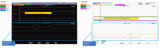
My customer is experiencing unstable linkup with DP83867IR, the issue descriptions are listed as below
| Scenario | Description | Occurrence | Note |
| 1 | Linkup fails occasionally when start up with Ethernet HUB and LAN cable connected | occasionally | |
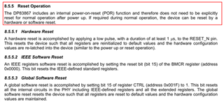
| 2 |
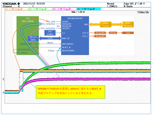
The LED connected to the LED_0 lights up as the reset(RESET-N pin) signal being removed |
Rarely | No linkup in this scenario |
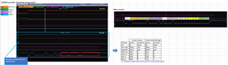
| 3 | All MDIO read returned 1 (DP83867 no response) | Rarely | No linkup in this scenario |
| 4 | MDIO read returned unexpected value | Rarely |
No linkup in this scenario Same value was returned until power reset |
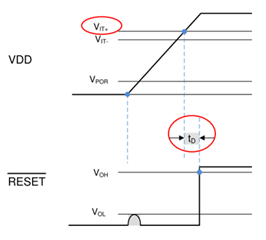
| 5 | Reset(RESET-N) does not work | Rarely | No linkup in this scenario |
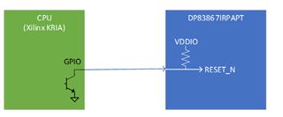
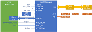
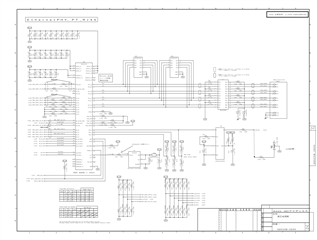
The block diagram and circuit are listed as below
Could you please advise on what could have caused this issue and the solution to it?
Regards