This thread has been locked.

If you have a related question, please click the "Ask a related question" button in the top right corner. The newly created question will be automatically linked to this question.

DP83TD510E: Question on DP83TD510E Tx and Rx termination

Part Number: DP83TD510E

Dear TI Experts,

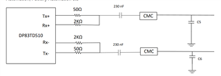
  In the datasheet of DP83TD510E, we can see for non-intrinsic safe, 50ohm is in series with Tx and 2kohm is in series with Rx and then they are combined together.

  We don't quite understand the reason why we use serial 50ohm to "terminate" Tx (Is that becase the source impedance of Tx driver is so small that we can neglect it?) and use 2kohm for Rx.

Would appreciate if someone can shed some light on this. Thanks.
Regards,

Yuanchen

  • Hi Yuanchen,

    I cannot reveal any details of the internal architecture of the device. Please follow the guidance given in the datasheet as this is how the part has been tested and verified.

    Thanks,

    David

  • Hello David,

      Understand, but we are not really asking for details of internal architecture. However, we just want to know what paramters we should understand and take for s parameter simulation for transmission line Tx and Rx communication respectively, based on the recommended schematics. Hope you can provide a bit more information of this device for us to understand and debug when problems occur or point out the document for this that we can refer to. Thanks.

    Regards,

    Yuanchen

  • Hi Yuanchen,

    The device has been tested and verified with the recommended circuit you see in the datasheet. Please follow this recommendation. If you have concerns about your design, I can review the schematic or layout. 

    Thanks,

    David

  • Hello, David

      Understand. Just one last question, we've seen from datasheet that DP83TD510E chip works in full-duplex mode, for which we take that transmit and receive actions are performed at the same time and we presume that tx and rx are in the same frequency range. Then How is full-deplex mode achieved? Would really appreciate if TI professional expert like you guys can explain a bit more about the thoery behind it, or kindly point out the document that we can refer to. (Is it done by predefined voltage levels range?)

    Thanks.

    Regards,

    Yuanchen

  • Hi Yuanchen,

    Full duplex mode uses a method called echo cancellation. The receiver knows what signal is being sent by the transmitter and can cancel it out via signal processing, leaving only the signal sent by the link partner. This is the reason for the 2kohm resistor connection between RX and TX pins. This is standard practice for 10Base-T1L.

    Thanks,

    David

  • Hi David,

    Thanks for your reply. I think I've gain a deeper understanding with your clarification in the aspect of 2kohm for local Tx to Rx path as to10M frequency signal.  Really appreciate your help.

    Regards,

    Yuanchen