This thread has been locked.

If you have a related question, please click the "Ask a related question" button in the top right corner. The newly created question will be automatically linked to this question.

TCA9555: Unable to send multiple I2C data to TCA9555PWR

Part Number: TCA9555
Other Parts Discussed in Thread: TM4C1292NCPDT, TCA6416,

Hi,

In my schematic, I'm connecting TM4C1292NCPDT to the IO expander IC TCA9555PWR through the I2C clock and data lines, SCL, and SDA. 

I'm trying to run the following code with all 3 address lines as HIGH which means address is 0x27:

#include <stdarg.h>

#include <stdbool.h>

#include <stdint.h>

#include "inc/hw_i2c.h"

#include "inc/hw_memmap.h"

#include "inc/hw_types.h"

#include "inc/hw_gpio.h"

#include "driverlib/i2c.h"

#include "driverlib/sysctl.h"

#include "driverlib/gpio.h"

#include "driverlib/pin_map.h"

#include "xdc/std.h"

#include <ti/drivers/I2C.h>

uint32_t g_ui32SysClock;

bool  bDiInitialized = FALSE;


#define DI_SLAVEADDRESS          0x27


//initialize I2C module 0

void InitI2C0(void)

{

   //enable I2C module 0

    SysCtlPeripheralEnable(SYSCTL_PERIPH_I2C0);

    //reset module

    SysCtlPeripheralReset(SYSCTL_PERIPH_I2C0);


    //enable GPIO peripheral that contains I2C 0

    SysCtlPeripheralEnable(SYSCTL_PERIPH_GPIOB);


    // Configure the pin muxing for I2C0 functions on port B2 and B3.

    GPIOPinConfigure(GPIO_PB2_I2C0SCL);

    GPIOPinConfigure(GPIO_PB3_I2C0SDA);


    // Select the I2C function for these pins.

    GPIOPinTypeI2CSCL(GPIO_PORTB_BASE, GPIO_PIN_2);

    GPIOPinTypeI2C(GPIO_PORTB_BASE, GPIO_PIN_3);


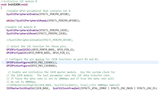
    // Enable and initialize the I2C0 master module.  Use the system clock for the I2C0 module.  The last parameter sets the I2C data transfer rate.

    // If false the data rate is set to 100kbps and if true the data rate will be set to 400kbps.

    //I2CMasterInitExpClk(I2C0_BASE, SysCtlClockGet(), true);//for 400kbps tm4c123

    I2CMasterInitExpClk(I2C0_BASE,  SysCtlClockFreqSet((SYSCTL_XTAL_25MHZ | SYSCTL_OSC_MAIN | SYSCTL_USE_PLL | SYSCTL_CFG_VCO_480),120000000), true);//for 400kbps tm4c129


    //clear I2C FIFOs

    //HWREG(I2C0_BASE + I2C_O_FIFOCTL) = 80008000;

}


//I2C Send Function

//sends an I2C command to the specified slave

void I2CSend(uint8_t slave_addr, uint8_t num_of_args, ...)

{

    uint8_t i ;

    // Tell the master module what address it will place on the bus when

    // communicating with the slave.

    I2CMasterSlaveAddrSet(I2C0_BASE, slave_addr, false);


    //stores list of variable number of arguments

    va_list vargs;


    //specifies the va_list to "open" and the last fixed argument so vargs knows where to start looking

    va_start(vargs, num_of_args);


    //put data to be sent into FIFO

    I2CMasterDataPut(I2C0_BASE, va_arg(vargs, uint32_t));

    //if there is only one argument, we only need to use the single send I2C function

    if(num_of_args == 1)

    {

        //Initiate send of data from the MCU

        I2CMasterControl(I2C0_BASE, I2C_MASTER_CMD_SINGLE_SEND);

        // Wait until MCU is done transferring.

        while(!(I2CMasterBusy(I2C0_BASE)));

        while(I2CMasterBusy(I2C0_BASE));

        //"close" variable argument list

        va_end(vargs);

    }

    //otherwise, we start transmission of multiple bytes on the I2C bus

    else

    {

        //Initiate send of data from the MCU

        I2CMasterControl(I2C0_BASE, I2C_MASTER_CMD_BURST_SEND_START);

        // Wait until MCU is done transferring.

        while(!(I2CMasterBusy(I2C0_BASE)));

        while(I2CMasterBusy(I2C0_BASE));

        //send num_of_args-2 pieces of data, using the

        //BURST_SEND_CONT command of the I2C module

        for( i = 1; i < (num_of_args - 1); i++)

        {     //put next piece of data into I2C FIFO

            I2CMasterDataPut(I2C0_BASE, va_arg(vargs, uint32_t));

            //send next data that was just placed into FIFO

            I2CMasterControl(I2C0_BASE, I2C_MASTER_CMD_BURST_SEND_CONT);

            // Wait until MCU is done transferring.

            while(!(I2CMasterBusy(I2C0_BASE)));

            while(I2CMasterBusy(I2C0_BASE));

        }

        //put last piece of data into I2C FIFO

        I2CMasterDataPut(I2C0_BASE, va_arg(vargs, uint32_t));

        //send next data that was just placed into FIFO

        I2CMasterControl(I2C0_BASE, I2C_MASTER_CMD_BURST_SEND_FINISH);

        // Wait until MCU is done transferring.

        while(!(I2CMasterBusy(I2C0_BASE)));

        while(I2CMasterBusy(I2C0_BASE));

        //"close" variable args list

        va_end(vargs);

    } }

//sends an array of data via I2C to the specified slave

void I2CSendString(uint32_t slave_addr, char array[])

    // Tell the master module what address it will place on the bus when communicating with the slave.

    I2CMasterSlaveAddrSet(I2C0_BASE, slave_addr, false);

     //put data to be sent into FIFO

    I2CMasterDataPut(I2C0_BASE, array[0]);

     //if there is only one argument, we only need to use the

    //single send I2C function

    if(array[1] == '\0')

    {

        //Initiate send of data from the MCU

        I2CMasterControl(I2C0_BASE, I2C_MASTER_CMD_SINGLE_SEND);


        // Wait until MCU is done transferring.

        while(!(I2CMasterBusy(I2C0_BASE)));

        while(I2CMasterBusy(I2C0_BASE));

    }

     //otherwise, we start transmission of multiple bytes on the I2C bus

    else

    {         //Initiate send of data from the MCU

        I2CMasterControl(I2C0_BASE, I2C_MASTER_CMD_BURST_SEND_START);

         // Wait until MCU is done transferring.

        while(!(I2CMasterBusy(I2C0_BASE)));

        while(I2CMasterBusy(I2C0_BASE));

         //initialize index into array

        uint8_t i = 1;

         //send num_of_args-2 pieces of data, using the

        //BURST_SEND_CONT command of the I2C module

        while(array[i + 1] != '\0')

        {            //put next piece of data into I2C FIFO

            I2CMasterDataPut(I2C0_BASE, array[i++]);

             //send next data that was just placed into FIFO

            I2CMasterControl(I2C0_BASE, I2C_MASTER_CMD_BURST_SEND_CONT);

             // Wait until MCU is done transferring.

            while(!(I2CMasterBusy(I2C0_BASE)));

            while(I2CMasterBusy(I2C0_BASE));

        }

         //put last piece of data into I2C FIFO

        I2CMasterDataPut(I2C0_BASE, array[i]);

         //send next data that was just placed into FIFO

        I2CMasterControl(I2C0_BASE, I2C_MASTER_CMD_BURST_SEND_FINISH);

         // Wait until MCU is done transferring.

        while(!(I2CMasterBusy(I2C0_BASE)));

        while(I2CMasterBusy(I2C0_BASE));

    }   }

 //I2C Receive Function

//read specified register on slave device

uint32_t I2CReceive(uint32_t slave_addr, uint8_t reg)

{    //specify that we are writing (a register address) to the

    //slave device

    I2CMasterSlaveAddrSet(I2C0_BASE, slave_addr, false);

    //specify register to be read

    I2CMasterDataPut(I2C0_BASE, reg);

    //send control byte and register address byte to slave device

    I2CMasterControl(I2C0_BASE, I2C_MASTER_CMD_BURST_SEND_START);

    //wait for MCU to finish transaction

    while(I2CMasterBusy(I2C0_BASE));

    //specify that we are going to read from slave device

    I2CMasterSlaveAddrSet(I2C0_BASE, slave_addr, true);

    //send control byte and read from the register we specified

    I2CMasterControl(I2C0_BASE, I2C_MASTER_CMD_SINGLE_RECEIVE);

    //wait for MCU to finish transaction

    while(!(I2CMasterBusy(I2C0_BASE)));

    while(I2CMasterBusy(I2C0_BASE));

    //return data pulled from the specified register

    return I2CMasterDataGet(I2C0_BASE);

}  }

void main(void)

{     // Set the clocking to run directly from the external crystal/oscillator.

   g_ui32SysClock = SysCtlClockFreqSet((SYSCTL_XTAL_25MHZ |

                                       SYSCTL_OSC_MAIN |

                                       SYSCTL_USE_PLL |

                                       SYSCTL_CFG_VCO_480),120000000);

   //initialize I2C module 0

  InitI2C0();

  I2CSend(DI_SLAVEADDRESS, 3, 0, 0, 0x01);

  I2CSend(DI_SLAVEADDRESS, 3, 0x06, 0x01, 0);//configuration port 0

    while(1){};

}

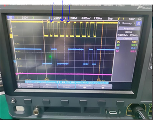
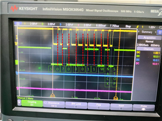
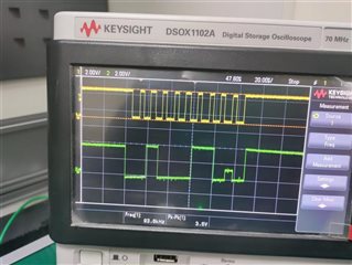
 But from the scope capture, only single I2C send command seems to be working not multiple.
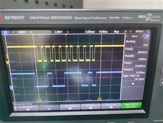
I checked the status register, I2C0MCS in debug mode of CCS. The DATACK and ERROR bits are set to LOW.
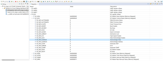
The pull-up resistors being used are 2K each. There's no scope captur showing ACK as LOW.

So,I used just one I2C write to the slave this time as suggested by you,i.e. I2CSend(DI_SLAVEADDRESS, 0, 0, 0, 0x01) but the scope capture remains the same.
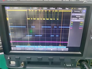
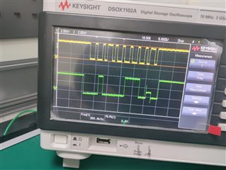
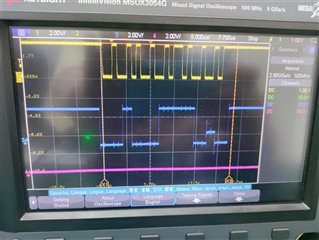
Additionally I tried the function I2CSend(DI_SLAVEADDRESS, 1, 0, 0, 0x01) for transmitting one bit and the scope capture was as below
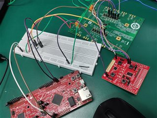
Also, I'm testing using Launchpad and EV-Boards of ADUM3151 isolator and IO-Expander EVM (setup shown below). I'm giving I2C SCL, SDA signals from Launchpad to IO Expander EVM via isolator.
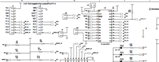
For the IO-Expander I'm using slave address as 0x27(screenshot of schematic given below), since all three address lines (Pins 2,3,21) in the EV-Board are pulled up (we've replaced the IC TCA6416 and soldered TCA9555PWR in the evaluation board).
But from the scope capture, only single I2C send command seems to be working not multiple.

Please guide for the same.

Best Regards,

Kiranjit

  • Kiranjit,

    It seems that your system does not have any I2C command working, not even a single one since it NACKs and stops further communication. 

    Can you help me understand how the clock is being generated?

    It seems that the clock is not consistent in its bit period. 

    Also, the bit marked here:

    Are we confident that on this rising edge of the clock that a "1" is being clocked? It seems very close to the edge of the SDA transition and is hard to tell if a "0" or "1" is being read. I2C requires a minimum data set-up time of 250ns for standard mode speeds (<100kHz). Setup time is the minimum time required for data to be stable on the SDA line after transitioning before it is sampled. 

    If this bit is being read as a "0" then you will end up with the wrong I2C address of course. Maybe try re-running the tests, but set A2 to "0" and see if the device ACK's.

    Regards,

    Tyler

  • You have shown three captures.

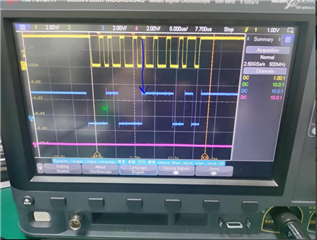
    In the first one, the SDA line changes at the same time as the rising edge on SCL. This is wrong, and might be interpreted as a STOP condition.

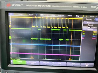
    In the second and third ones, the SDA line shows overshoots at the rising edges. This indicates that the pin is configured as a push/pull output, and not as a bidirectional open-drain pin as required for I²C. This has the effect that the slave is not able to send the ACK bit.

    All this implies that the I²C module and pins are not configured correctly. (I do not know anything about the TM4C.)

  • Hi Tyler and Clemens,

    I tried setting A2 as '0' and so, given 0x23 as address (see scope capture). 

    My code is already attached in the previous post. Please suggest how do I provide proper setup time through this code?

    Also, I'm using I2C0 (PB2, PB3) for SCL and SDA in cde and those are the 2 lines I'm giving to my IO expander after pulling up with 2k.

    Please give feedback on how and where I need to make the changes.

    Best Regards,

    Kiranjit
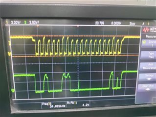
  • This waveform again has a rising edge on SCL and SDA at the same time, which is not allowed. And the SDA pin does not appear to be configured as an open-drain pin (which implies that the GPIOPinTypeI2C(GPIO_PORTB_BASE, GPIO_PIN_3) call did not work).

    I do not know about the TM4C. This should be moved to the microcontrollers forum.

  • Kiranjit,

    I second Clemens answer on the rising edge on SCL.

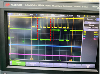
    If you look at the red lines, the SCL is sampling SDA on the edge transition rather than 50% into the data bit. Something is wrong with the timing here, which is probably an error in the setup of the I2C signaling. 

    If you need an answer faster, I could move this thread to the microcontroller forum for TM4C arm-based microcontrollers. They might have more support from a coding perspective. 

    I can look at the code and get a response to you by tomorrow 5pm CST. 

    Regards,

    Tyler

  • Hi Tyler,

    Please see if you can check the code.

    I had already put this on the microcontroller forum but didn't get help there. Please see link below:

    TM4C1292NCPDT: unable to send multiple I2C data to TCA9555PWR - Arm-based microcontrollers forum - Arm-based microcontrollers - TI E2E support forums

    Maybe if you could put it in your own words in terms of timings then please do

    And I've configured both SCL and SDA as open drain and pulled up both.

    Thanks,

    Kiran

  • Hi Kiran,

    Here is my best guess to what is happening right now. Based on the scope capture, it is looking like the rising edge of the clock is sampling on the rising edge of the data line (SDA). This is not how I2C works. The clock signal should be sampling about 50% into the data bit, not right at the edge. Because the clock signal is sampling on the edge of the bit, it may clock in data of "1" or "0" data is uncertain. 

    Your scope capture shows 7-bit address followed by a write bit followed by a NACK, since SDA is HIGH on the 9th clock edge. 

    This is telling me that the target/slave device did not recognize the I2C address, and this might possibly be due to a bad timing.

    I am trying to follow page 8-9 of this application report here and comparing it with your code. 

    https://www.ti.com/lit/an/spma073/spma073.pdf?ts=1676562493313&ref_url=https%253A%252F%252Fwww.google.com%252F

    You define a slave address above:

    #define DI_SLAVEADDRESS          0x27

    but your scope capture shows:

    0x27 is the address you are attempting to send: 0100111

    We are seeing in the scope 0?00011

    which is wrong regardless of whether the "?" is a "1" or "0". We are sending an address that the device does not recognize, and I think this is a timing issue. I don't think the error lies in the I2Csend or I2Creceive commands. I would think this error would occur in the INIT function.

       //enable I2C module 0

        SysCtlPeripheralEnable(SYSCTL_PERIPH_I2C0);

        //reset module

        SysCtlPeripheralReset(SYSCTL_PERIPH_I2C0);


        //enable GPIO peripheral that contains I2C 0

        SysCtlPeripheralEnable(SYSCTL_PERIPH_GPIOB);


        // Configure the pin muxing for I2C0 functions on port B2 and B3.

        GPIOPinConfigure(GPIO_PB2_I2C0SCL);

        GPIOPinConfigure(GPIO_PB3_I2C0SDA);


        // Select the I2C function for these pins.

        GPIOPinTypeI2CSCL(GPIO_PORTB_BASE, GPIO_PIN_2);

        GPIOPinTypeI2C(GPIO_PORTB_BASE, GPIO_PIN_3);


        // Enable and initialize the I2C0 master module.  Use the system clock for the I2C0 module.  The last parameter sets the I2C data transfer rate.

        // If false the data rate is set to 100kbps and if true the data rate will be set to 400kbps.

        //I2CMasterInitExpClk(I2C0_BASE, SysCtlClockGet(), true);//for 400kbps tm4c123

        I2CMasterInitExpClk(I2C0_BASE,  SysCtlClockFreqSet((SYSCTL_XTAL_25MHZ | SYSCTL_OSC_MAIN | SYSCTL_USE_PLL | SYSCTL_CFG_VCO_480),120000000), true);//for 400kbps tm4c129

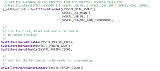
    This part of your code. Can you follow the example on page 9 of the attached application report?

    setup the system clock first, then stop the clock, reset, and enable I2C module, then wait for peripheral to setup: while(!SysCtlPeripheralReady(SYSCTL_PERIPH_I2C2)); <- this is not in your code. 

    I also think your code might be lacking the I2CMasterIntEnableEx function call to enable your interrupts for arbitration lost, stop bit, nack bit, clock low timeout and data. Can you try calling this function in your INIT function?

    Regards,

    Tyler

  • Hi Tyler,

    I did the following changes in the code.

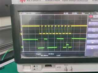
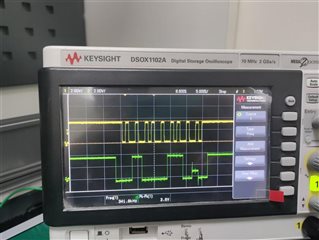
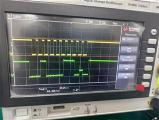
    Please see the scope capture for pull up of SDA and SCL with 2k (100kHz and 400kHz respectively)

    100kHz

    400kHz

    Scope capture for pull up of SDA and SCL with 4k7 (100kHz and 400kHz respectively):

    100kHz

    400kHz

    Please share your feedback.

    Best Regards,

    Kiran

  • Kiran,

    What external oscillator are you using? Can you replace it with another oscillator/crystal? 

    It seems that the clock signal for 100kHz is fine. 

    400kHz looks to be where the clock signal is breaking down and no longer consistent. It seems some pulses are longer than others for some reason. 

    Can you change pull-up resistors from 2k to 10kohm? 

    Scope capture:

    I2C bus is still sending wrong address. 

    0x27 = 0100111

    scope = 0100011

    I also don't understand why the bus is half-way in between a NACK and ACK. The scope should show a complete NACK since the device is receiving a wrong I2C address. 

    The SDA lines seem to be push-pull rather than open drain which possibly is an error in configuration. 

    GPIOPinConfigure(GPIO_PL1_I2C2SCL);

    GPIOPinConfigure(GPIO_PL0_I2C2SDA);

    GPIOPinTypeI2C(GPIO_PORTL_BASE, GPIO_PIN_0);

    GPIOPinTypeI2CSCL(GPIO_PORTL_BASE, GPIO_PIN_1);

    Can you reconfigure your I2C SDA and SCL lines to configure first, then adjust the pin type with corresponding port_base and GPIO pin using the code I provided?  (this is from the attached document page 8 here)

    If this doesn't work, please try pulling "A2" HIGH, and try resending the commands again. 

    Lets try to get this system working at slower speeds of 100kHz. If we can get 100kHz working, then we can move on to faster communication speed of 400kHz.

    Regards,

    Tyler

  • Hi Tyler,

    What external oscillator are you using? Can you replace it with another oscillator/crystal? 

    >>> What external crystal are you referring to, because we're using evaluation boards for both the microcontroller, tm4c1292ncpdt (TI launchpad) and IO expander, TCA9555pwr. So, the external crystal is already placed in the boards.

    Can you change pull-up resistors from 2k to 10kohm? 

    >>> Changed the pull-up resistors to 10k.

    I2C bus is still sending wrong address. 

    0x27 = 0100111

    scope = 0100011

    >>> The address being sent is 0x23 only and not 0x27.

    Can you reconfigure your I2C SDA and SCL lines to configure first, then adjust the pin type with corresponding port_base and GPIO pin using the code I provided?  

    >>> Please check that I configured the pins the same way as you've suggested.

    Please see the scope capture for 100kHz frequency

    Best Regards,

    Kiranjit
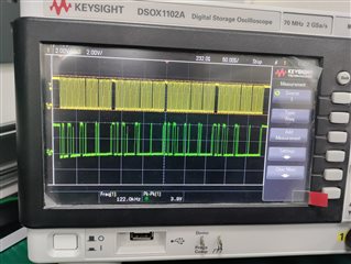
  • Kiranjit,

    Sorry for the delay, Monday was President's day, and most of the team was out of office.

    Disregard my comment on the external oscillator, for some reason, I thought you were using your own oscillator in your design rather than the one implemented on the PCB. 

    I2C bus is still sending wrong address. 

    0x27 = 0100111

    scope = 0100011

    Did you try my suggestion of externally setting A2 = LOW on the TCA9555 to see if the I2C controller continues communication with correct address? It also looks like the ACK bit voltage is a little high for a VOL. This is why I was suggesting implementing weaker pull-up resistors to see if the driver could push that voltage closer to GND. 

    The changes in code look like the document. The only other thing I can think of at the moment is to go through the pdf that I have attached:

    https://www.ti.com/lit/an/spma073/spma073.pdf?ts=1676562493313&ref_url=https%253A%252F%252Fwww.google.com%252F

    and make sure that each step is being followed in your code. 

    As for more things to try:

    Can you run this command after initialization SysCtlPeripheralPresent(SYSCTL_PERIPH_GPIOB) to check to make sure this returns "TRUE." I want to make sure that the peripheral is present. 

    Since your INIT function seems solid, I think we can narrow down the issue somewhere inside the I2CSend() function. Originally I was thinking something was wrong in the setup, but now I think the error might be in the actual transaction. 

    What code is associated with this function: va_start()? 

    What are the parameters to the I2CSend() function?

    Regards,

    Tyler

  • Hi,

    Did you try my suggestion of externally setting A2 = LOW on the TCA9555 to see if the I2C controller continues communication with correct address? It also looks like the ACK bit voltage is a little high for a VOL. This is why I was suggesting implementing weaker pull-up resistors to see if the driver could push that voltage closer to GND. 

    >>> Yes, I had connected A2 to GND externally.

    The changes in code look like the document. The only other thing I can think of at the moment is to go through the pdf that I have attached:

    https://www.ti.com/lit/an/spma073/spma073.pdf?ts=1676562493313&ref_url=https%253A%252F%252Fwww.google.com%252F

    and make sure that each step is being followed in your code. 

    >>> In this pdf, only the names of example codes are given and not the actual codes, e.g., ektm4c129_i2c_master_cpu_nonfifo, ektm4c129_i2c_master_cpu_fifo etc. Are there any source code files of these example codes?

    What code is associated with this function: va_start()? 

    >>> The following is the definition of 'va_start'

    What are the parameters to the I2CSend() function?

    >>> The definition of I2CSend function is: void I2CSend(uint8_t slave_addr, uint8_t num_of_args, ...)

    Another thing I wanted to ask was do I need to add the interrupt for I2C receiver to read if the received FIFO of I2C is FULL?

    Best Regards,

    Kiranjit
  • Kiranjit,

    >>> In this pdf, only the names of example codes are given and not the actual codes, e.g., ektm4c129_i2c_master_cpu_nonfifo, ektm4c129_i2c_master_cpu_fifo etc. Are there any source code files of these example codes?

    TI does not provide source code for these devices. Our team has not generated any code for this device. 

    While we don't provide code, I'll do my best to debug your code in question, but please note that my bandwidth to help you is limited. 

    Texas Instruments offers an I2C_api library here:

    https://software-dl.ti.com/simplelink/esd/simplelink_msp432e4_sdk/2.30.00.14/docs/driverlib/msp432e4/html/group__i2c__api.html

    I believe this library can be used for the TM4C series. 

    >>> The definition of I2CSend function is: void I2CSend(uint8_t slave_addr, uint8_t num_of_args, ...)

    I see "uint8_tslave_addr, uint8_tnumof_args,...) " but what are the other parameters within this function call?

    Another thing I wanted to ask was do I need to add the interrupt for I2C receiver to read if the received FIFO of I2C is FULL?

    Interrupt (/INT) is an output that is generated by any rising or falling edge of the port inputs in input mode. Resetting the interrupt circuit is achieved when data  on the port is changed to the original setting or data is read from the port that generated the interrupt. Resetting occurs in the read mode at the ACK bit. 

    The va_start function call is not really telling me anything. I don't know where this call is coming from or what it does for the I2Csend function. 

    Is it possible to test your system with only the TM4C and the IO expander connected leaving the SPI isolater out of the equation? I am not familiar with the ADUM3151, but would this device possibly be causing issues to the SDL/SCL bus? 

    Regards,

    Tyler

  • Hi Tyler,

    Yes, you're right/ It looks like you're right about the isolator.

    I checked without the isolator and following was the result.

    Also, I changed the code to directly use the functions for sending the data in the main itself after initialization as below and didn't use the function I2CSend() this time.

    InitI2C0();

    I2CMasterSlaveAddrSet(I2C0_BASE, DI_SLAVEADDRESS, false);
    I2CMasterDataPut(I2C0_BASE, 0x1);

    I2CMasterControl(I2C0_BASE, I2C_MASTER_CMD_SINGLE_SEND);

    //Initiate send of data from the MCU

    // Wait until MCU is done transferring.
    while(!(I2CMasterBusy(I2C0_BASE)));
    while(I2CMasterBusy(I2C0_BASE));

    //I2CMasterDataPut(I2C0_BASE, g_ui8MasterTxData[g_ui8MasterBytes++]);

    while(1){};

    Thanks a lot for your help.

    I will check again by putting the frequency compatible isolator.

    Best Regards,

    Kiran

  • Hi Kiran,

    The Engineer supporting this issue is currently out. He will provide feedback (as needed) next week. Thank you for your patience!


    Regards,
    Jack 

  • Hi Kiran,

    Did writing code in main() function instead of using I2CSend() have any positive effect on the problem? I don't see why this would solve the issue since the code is nearly the same. 

    As for the scope capture, the I2C signals look worse. Are you getting good read and writes with your system? Is I2C communication possible? 

    Any update on the frequency compatible isolator? 

    Regards,

    Tyler

  • Hi Tyler,

    Did writing code in main() function instead of using I2CSend() have any positive effect on the problem? I don't see why this would solve the issue since the code is nearly the same. 

    >>> There was no difference due to writing the code in the main() function.

    As for the scope capture, the I2C signals look worse. Are you getting good read and writes with your system? Is I2C communication possible? 

    Any update on the frequency compatible isolator? 

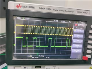
    >>> Yes, we received the new isolator ADUM1250 EV-Board and checked the output. Following are the scope captures using this isolator for 400kHz.

    Best Regards,

    Kiranjit
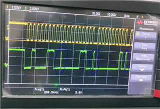
  • Kiranjit,

    It looks like the waveforms are okay except for a couple artifacts occuring on the SDA line. Are those voltage spikes expected based on the data you are trying to send? I don't think these are proper I2C signals. 

    Regards,

    Tyler