This thread has been locked.

If you have a related question, please click the "Ask a related question" button in the top right corner. The newly created question will be automatically linked to this question.

DS90UB960-Q1: DS90UB960-Q1; How to program some physical I2C slave address of DS90UB960/DS90UB953.

Part Number: DS90UB960-Q1

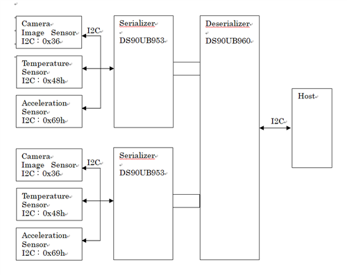
 In this case of the I2C connection block diagram below, please tell me the register settings for us.
In particular, A lot of I2C devices are connected to one serializer. And, a device with the same I2C register address is connected to each serializer.

Q)Please tell me the register settings.


 Especially below.

- SER_ID
- SER_ALIAS_ID
- SER_ID
- SER_ALIAS_ID

  • Hello,

    For this configuration, there are two general registers that need to be set before an alias or an ID is assigned to any of the target devices or serializers.

    First, the two RX ports being used need to be mapped to the specific I2C port that the Host device is using. This mapping is done by setting the corresponding bits in Register 0x0C. By default, all RX ports will be mapped to I2C Port 0. If you are using I2C Port 1 instead of I2C Port 0 for your application, then you can use this register to remap the I2C port to the RX ports being used. 

    Next, the I2C pass through bit (Bit 6, Register 0x58) needs to be set for both of the RX ports being used. Since this register is an RX port-specific register, writes need to specifically be enabled for both of the RX ports being used before any data is written to Register 0x58. To enable writes for both RX ports, you need to set the corresponding bits in register 0x4C. Once writes are enabled for the specific RX ports being used, you can then enable I2C pass through for both RX ports. This action can be done simultaneously for both RX ports if writes are enabled for both ports. After I2C pass through is enabled for both bits, I recommend disabling writes for both registers, since the next step will require you to only write to one RX port at a time.

    For your application, I am assuming that you want the ability to independently communicate with each of the 6 remote target devices connected to the I2C bus. If this is not the case, please let me know. 

    To communicate with only one of the 6 possible remote target devices during a single I2C transaction, each target device needs to be assigned a different alias. This is done by assigning a different 7 bit alias for each of the target devices using registers 0x65-0x6C. Each of the 6 different alias identifiers have to be different from each other in order for the host to be able to communicate independently with each of the 6 target devices. For each alias, the I2C physical address needs to be set in the corresponding ID registers (0x5D-0x65) so that the device can properly decode each transaction. Each Alias and ID register is a port specific register, and only one of the port specific registers should be enabled at a time when performing a write command. If not, 3 of the target devices will share the same alias. To simplify the procedures that I have outlined, I recommend that you follow these steps:

    1. Enable writes on only one of the two RX ports that are being used.

    2. Load in the physical I2C address for the camera sensor, the temperature sensor, and the acceleration sensor in three of the ID registers (0x5D-0x5F)

    3. Assign an alias for each of the three IDs in three of the alias registers (0x65-0x67). Note: the # of the alias register and the # of the ID register need to match. For example, alias register #0 is the alias for the I2C address in ID register #0. 

    4. Disable writes for the RX port where alias and ID bits were previously assigned, and enable writes for the RX port where alias and ID bits have not yet been assigned. 

    5. Repeat steps #2-#3, this time for the other RX port. Please keep in mind that even though you are now assigning alias and ID information for a different RX port, each alias that you assign needs to be different from the assigned alias values in the previous RX port. To communicate with each of the 6 target devices independently, 6 unique alias values are required. 

    Following these steps above should allow you to independently communicate with each target device by using the assigned alias value. To independently communicate with each serializer, you need to follow a similar series of steps:

    1. Enable writes on only one of the two RX ports being used.

    2. Assign an alias for the serializer using the SER_ALIAS_ID register (register 0x5C)

    3. Disable writes for the RX port where the SER alias was previously assigned, and enable writes for the RX port where the SER alias has not yet been assigned. 

    4. Repeat step #2.

    Following the steps above should allow you to independently communicate with each serializer in your application.

    If you have any questions about the steps above, please let me know.

    Regards,

    Kenneth

  • Hello Kenneth,

    Thank you answering my questions. I understood some questions by your kindness explanation. If I have more question, I 'll ask you again.

    Thank you.

    Regards,
    Shuichi Sugi.