This thread has been locked.

If you have a related question, please click the "Ask a related question" button in the top right corner. The newly created question will be automatically linked to this question.

TCA9546A: VCC design in 1.8V/3.3V for VPass application

Part Number: TCA9546A

Hi TI team,

We want to use TCA9546A on our design, but we have concern for datasheet.

Please refer our diagram.

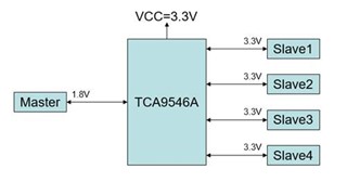
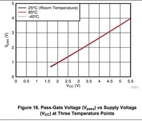
VCC=3.3V and Vpass is about 1.9V .
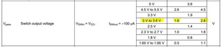
About Vpass min is 1.6V on VCC 3V to 3.6V.

In order for the TCA9546A to act as a voltage translator, the Vpass voltage must be equal to or lower than the lowest bus voltage.

If our design in VCC=3.3V case, our master use 1.8V but Vpass is in 1.6V-2.8V.

We're worried about this in 1.8V master side.
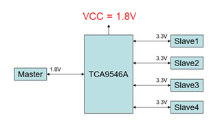
Do you have experience and suggestion for this design? Do we have any risk? or we must change to VCC in 1.8V.

BR,

Helen

  • Your worries are justified; a VCC of 3.3 V is too high to allow 1.8 V signals.

    You must use a lower VCC, e.g., 1.8 V.

  • Hi Clemens,

    Got it.

    Please kindly help us to check our slave side in 3.3V. Is there any risk in VCC set 1.8V?

    And please provide the pull resistors value for our reference if TI team have suggestion.

    Our slave sign is design pull up in 2K ohm and in 3.3V.

    Many thanks.

    BR

    Helen

  • I²C is a bidirectional protocol; there is no electrical difference between masters and slaves.

    The switches are closed for voltages below Vpass, and open for larger voltages. In the latter case, the voltage on all bus segments is determined by the pull-up resistors.

    The pull-up resistors on all enabled bus segments act in parallel. So the total current through the resistors on all enabled bus segments should be below the I²C limit, which is 2 mA for a low-voltage bus. So assuming that only one slave channel is enabled at a time, each pull-up resistor should be no stronger than 1 mA.

    Also see the I2C Bus Pullup Resistor Calculation application report, but note that you have multiple resistors in parallel.

  • Hi Helen,

    Clemen's answer is correct. I would also recommend looking at the app note he referenced if you need suggested pull up resistor values. 2.2k pull ups on a 3.3V logic seems like it would work if the block diagram you provided is accurate (1x I2C target device on each channel).

    Let us know if you still have any other questions or concerns.

    -Bobby 

  • Hi Clemens and Bobby,

    For the "pull-up resistors on all enabled bus segments act in parallel" , will the pull-up resistors of both master side and slave side act in parallel ,too? If it does , is there any risk of  pull up the master side and slave side on the same bus with 2 different power rail?

    Thanks

    Bart

  • Yes; there are five bus segments, one with the master, and the four slave segments.

    The TCA9546A blocks high voltages; the segments are connected only when the signal is low.

  • will the pull-up resistors of both master side and slave side act in parallel ,too?

    As Clemen's pointed out, they are only acting in parallel when the signal is low.

    is there any risk of  pull up the master side and slave side on the same bus with 2 different power rail?

    No risk if you make Vcc=1.8V on the I2C switch. The high signals will be blocked.

    -Bobby

  • Hi Clemens,

    Since it connected to each side (master and  slave) when the signal is low , I think it may be ok for the disign with different power rail.

    Thanks for your valuable comments.

    Bart

  • Thanks Bobby.