This thread has been locked.

If you have a related question, please click the "Ask a related question" button in the top right corner. The newly created question will be automatically linked to this question.

TIOL1115: How to connect TIOL1115 for an IO-Link Project? Is TIOS101 also needed for the sensors?

Part Number: TIOL1115
Other Parts Discussed in Thread: TIOS101

Hello,

My main application is to integrate the magnetic reed sensor switch to activate and deactivate the output which are pilot valves.

I had planned to connect the sensors directly to the microcontroller as DI and the also the pilot valves as DO and use the USART from microcontroller to communicate between the IO-Link master via the TIOL1115 IO-Link PHY.


Is my approach the correct way? Or should I rather integrate the sensors with TIOS101 as it is a digital sensor output driver and also use the TIOL1115 as the IO-Link PHY.
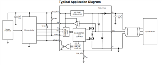
TIOL111 application diagram

  • Hi Chirag,

    You could implement this either way and it is just a matter of how you want to structure the communication with the Master and the software in both the local device microcontroller and in the Master.

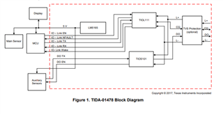
    If I understand your planned approach, the microcontroller will monitor the magnetic reed switch state and then relay this information to the Master through an IO-Link message passed through the TIOL1115 from the USART port.  If the voltage levels of the magnetic reed switch and the pilot valves are compatible with the microcontroller, this is a valid approach.

    The other option you have suggested also could work and it would require the Digital Input wire in the Master port to be used as well as the IO-Link CQ wire.  When the magnetic reed sensor activates, the TIOS101 would drive the DI input of the Master which would in turn have be programmed to respond accordingly.  I would assume this means it would then have to send a message back to the device across the CQ wire and tell the microcontroller to control the pilot valves. 

    This second approach might have longer latency than in your first planned option, but it certainly could work as well.  I believe the first option has the lowest response latency because the local device microcontroller would not have to first communicate with the Master before acting on the state change of the magnetic reed switch and it could still pass the status information to the Master across the CQ wire. 

    If the microcontroller is not capable of driving the pilot values directly, the TIOS101 could possibly be an option control the valves and isolate the drive current from the microcontroller.  This would essentially be a third configuration and is a modification of your first planned option.

    So, in summary, I think your first approach is a good one as long as the micrcontroller can handle direct connections to the switches and valves.  Otherwise a slight modification to this approach may be needed such as using the TIOS101as a buffering device.  But a large portion of this decision comes from how you want to structure the software or application firmware.

    Regards,

    Jonathan

  • Hello Jonathan, 

    Thanks for the detailed response.

    Yes, i totally agree with you about my first approach. Unfortunately the pilot valves and the reed switches do not match the voltage requirements for the microcontroller, therefore i have planned to connect it to the micrcontroller via an optocoupler and a relay module where i regulate the voltage to get into the microcontrollers range.