This thread has been locked.

If you have a related question, please click the "Ask a related question" button in the top right corner. The newly created question will be automatically linked to this question.

SN65LVDT14-EP: Increased Bypass Capacitor on Bias power

Part Number: SN65LVDT14-EP
Other Parts Discussed in Thread: AMC1304L05, SN65LVDT14

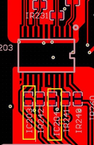
Since the radiation problem, customer tried to create the bypass capacitor at the bias power rail from 0.1uF to 0.47uF. As a result, the radiation emission can be reduce more than 2dB and keep more design margin.

But there is no suggestion value on the d/s. is 0.47uF ok or not based on device design's prospective? or what related electrical needs to be verified? Very thanks.  

Application: Motor Drive

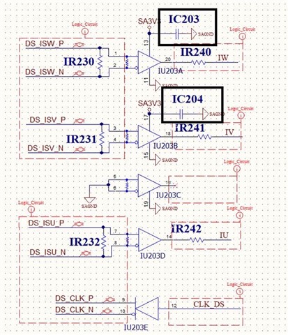
Use case: AMC1304L05 + SN65LVDT14 for phase current sensing of the motor.

  • See section 9.2.2.4 of the SN65LVDT14 (without -EP) datasheet. It recommends 100 nF and 1 nF in parallel, with the smaller capacitor closest to the chip. ("Smaller" means the smallest package with the lowest inductance.)

    On your board, the capacitors are close to the chip, but the SAGND connections go elsewhere through long traces. Is there no ground plane?

  • For the better RE performance in the system, the bypass cap needs up to 0.47uF. If this is a case, ss there concern or side effect regarding device's prospective? Is the peak sinking/sourcing current of VCC pin able to sustain this surge current during operation?

    the working freq. is about 20MHz with ISO modulator.

    Regards

    Brian  

  • The 100 nF + 1 nF recommendation is for boards that also meet the other recommendation laid out in section 9.2.2 and 11.1 of the SN65LVDT14 datasheet.