This thread has been locked.

If you have a related question, please click the "Ask a related question" button in the top right corner. The newly created question will be automatically linked to this question.

P82B715: Design help for multiple bus expanders

Part Number: P82B715


Hi Experts,

Seeking your assistance on this query from Cx about P82B715 bus expander.

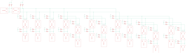
For this I have built a network (see schematic2.png), which unfortunately cannot be simplified further. A microcontroller sits with the first P82B715 in a distribution. The I/O expander, sensor 1, sensor 2, sensor 3, sensor 4, sensor 5 are connected star-shaped with the first expander. The meter value 7 m e.g. stands for the distance from the first expander to the expander of sensor 1.
The expanders of sensor 6 and sensor 7 are connected in parallel to the expander of sensor 5 and have no direct connection to the first expander.
Each of the .1 sensors are always connected in parallel to the main expander from the sensor with a cable length of 0.3m.
The used cable type is Cat 7 and all components are powered with 5V.
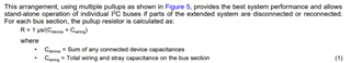
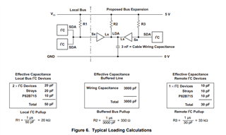
In the datasheet there is a chapter for the calculation of the pullup resistors. Unfortunately I didn't understand it yet.
In the schematic I have drawn all possible pullup resistors.

[1] First the general question, can I build the network like this?
[2] Which resistors do I really need?
[3] And how big do the resistors have to be?

I would be very grateful if device expert could get some information about this.

Regards,
Archie A.

  • 1. Yes.

    2. Pull-up resistors belong to the bus, not to each device. You need only one pair on the long bus segment. (Except when you might disconnect some cables.)

    3. Estimate the bus capacitance, and compute what resistors you need for your desires speed. Or just look at the waveforms with an oscilloscope, and adjust the resistors as needed. (If you have multiple resistors in parallel, use larger values so that the total resistance is correct.)

    4. Please note that twisted pairs are designed for differential signals. If you run two separate signal over a twisted pair, you will get crosstalk.

  • Hi Clemens and Experts,

    Thanks for the inputs and sharing this information.

    For the twisted pair cables, as specified in the datasheet, we use one pair with 5V and Lx and the other pair is with GND and Ly. So the crosstalk should be suppressed or?

    Unfortunately, we don't have an oscilloscope and can't analyze the bus signal. What values do we still need to determine so that you can determine the resistors? According to the data sheet of the cable, the capacitance is 1.5 pF/m, but there is no frequency specification.

    Our bus frequency is 100 kHz.

    We would be very grateful to determine the resistors with concrete values and also which resistors can be removed. Thanks ahead, Experts.

    Regards,
    Archie A.

  • Pairing Lx with Ly would be bad. The datasheet recomments pairing the signals with 5V/GND so that the signal crosstalk goes into the power supply. But you would get even less crosstalk if you'd use both lines in the pair for the same signal, which increases the number of pairs to three or four. (I don't know if you have that many pairs available.)

    As a rule of thumb, a 400 pF bus running at 400 kHz might need a pull-up current of 6 mA. So you will need about 6 mA × (100 kHz / 400 kHz) × (Ctotal / 400 pF).

    You can keep R3/R8, and remove all other resistors on the same line (R4/R5, R9/R10, …, R53/R54).

  • Hi Archie,

    For the twisted pair cables, as specified in the datasheet, we use one pair with 5V and Lx and the other pair is with GND and Ly. So the crosstalk should be suppressed or?

    I think to Clemens' point is that this is okay. 5V pair with Lx, and GND with Ly should be okay. Problems occur when pairing Lx and Ly in the twisted pair cable. This will make X-talk much worse this way. 

    I2C specifies a maximum rise-time of 1000ns (1us) at 100kHz operation. As an approximation, you can take the product of net resistance and net capacitance and ensure that this value is 1us or less. This will satisfy the total system rise time. 

    You can estimate the amount of bus capacitance by taking the 1.5pF / m for the cable, 10pF / device present, and 1pF-3pF / inch of PCB trace capacitance (if PCB is used). 

    Using page 10 on the datasheet, you can use equation (1) in order to estimate the pull-up resistance required on the buffered side. 

    What would the customer say is the total amount of cabling that will be used? Once you find the total amount of cabling, you can take (meters of cable) x 1.5pF / m + (10pF x 14 devices) + (3pF x inchs of trace) = total parasitic bus capacitance. 

    Then, use this value to estimate the pull-up resistance required based off 1 us approximation. 

    Regards,

    Tyler

  • Hi Clemens and Tyler,

    Thank you for your guidance and explanations.

    We have a total of 37.8 m of cable, 14 ICs and 7 inches of PCB. This gives them a resistance of around 4600 ohms. How do we distribute this resistance now?

    In the datasheet, it says that each bus node is looked at individually. Can you give us some help on how we should distribute the resistors?

    If we always place resistors at the farthest ends of the bus and at the first P82B715 and their parallel sum equals the 4600 ohms, would that be okay?

    So R3, R8, R4, R5, R9, R10, R13, R14, R21, R22, R29, R30, R37, R38, R45, R46, R53, R54.

    At the moment we have 4.7 kOhm resistors on each S side (R1, R2, R6, R7, R11, R12, R15, R16, and so on). Can these stay or do they need to be tuned as well?

    Regards,
    Archie A.

  • Archie,

    If we always place resistors at the farthest ends of the bus and at the first P82B715 and their parallel sum equals the 4600 ohms, would that be okay?

    Yes this would work, but I do not think this is necessarily required for the device due to such low operation speeds <100kHz. Having 1 pair of pull-up resistors each valued at 4600 ohm for the Lx/Ly lines is fine (R3/R8). 

    In systems that experience higher speeds (like CAN bus) termination at opposite nodes of the system are needed due to reflections on the signal pair. For I2C operation in this customer case, I don't think we will need to worry about that. 

    If the customer decides to terminate each node, then the parallel combination of all the pull-up resistors needs to equate to 4600 ohms. This will end up using fairly large resistors, and a lot of them which takes up space on the PCB. 

    So R3, R8, R4, R5, R9, R10, R13, R14, R21, R22, R29, R30, R37, R38, R45, R46, R53, R54.

    At the moment we have 4.7 kOhm resistors on each S side (R1, R2, R6, R7, R11, R12, R15, R16, and so on). Can these stay or do they need to be tuned as well?

    Pull-ups placed on the Sx/Lx lines can be tuned as follows according to figure 6. in the datasheet:

    The pull-up resistance for each bus can be tuned according to the total parasitic bus capacitance present on the node. 

    Regards,

    Tyler