This thread has been locked.

If you have a related question, please click the "Ask a related question" button in the top right corner. The newly created question will be automatically linked to this question.

TCA9803: Configuring multiple slave boards with TCA9803 devices on all boards

Part Number: TCA9803
Other Parts Discussed in Thread: TCA9800, TCA9517, TCA9509

Our new product has the following I2C configuration:

  • One I2C bus master board and 5 slave boards, all on the same bus
  • Boards are connected by short cables
  • All boards run at 3.3V

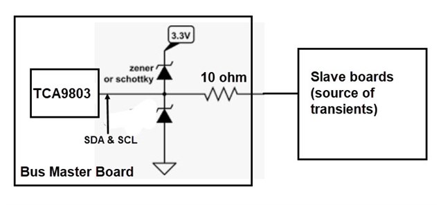
We want to put TCA9803 devices on the master and slave boards in the following configuration. Our use case is buffering only, without level-shifting. Can you please confirm that this setup is correct? Thank you!

We want to thank the TI team for offering (by far) the best I2C product line! We always turn to TI for all our I2C device needs.

  • Such a setup is possible; connecting A⟷B is allowed, also in series, and with multiple A sides.

    But note that you must not connect any pull-up resistors on any B side; remove the pull-ups on the large bus segment.

    If the slave boards are not large, you can use TCA9800 on them. (The only difference between TCA9800/1/2/3 is the B-side current source.)

  • Thanks so much, Clemens! We really appreciate your fast and clear reply. My final question is about device selection within the TCA980x family. The datasheet says, "it is acceptable to select the TCA9803 as the default." Is there any advantage to optimizing the device selection (and considering TCA9800)? Or should we just use TCA9803 at all locations, given that it has the strongest drive? Power consumption isn't a concern in our application.

    You guys are the best!

  • Higher current implies higher power usage. If you do not care, just use the -3.

  • Thanks again, Clemens, for your super-fast resolution! To close off this thread, I've posted below our final system diagram showing our bus master board and five slave boards with TCA9803 buffers on all boards. This diagram has two changes from the one I originally posted above:

    • I removed ALL the pull-up resistors from the TCA9803 "B" sides (in my earlier diagram, I left in one pair by mistake).
    • I added 12V and GND lines to make clear that 3.3V power at the slave boards is locally regulated. Our board-to-board cabling has four wires: 12V, SDA, SCL, GND.

    Clemens, can you please take a quick look and verify that this final diagram is completely correct?

  • Looks fine. (Assuming that things like decoupling capacitors are implied.)

  • Thanks! Yes, we will follow the datasheet's advice to put 0.1 μF and 1 μF capacitors as close as possible to the VCCA and VCCB pins.

  • Thanks for the help Clemens!

    Virtuix,

    Please let us know if you have any other questions.

    Regards,

    Eric Hackett

  • Hi Eric and Clemens, we ran into some difficulties today with our initial TCA9803 test setup and would like to get your advice.

    Background information:

    • Our I2C bus system has a bus master board that connects to five slave boards. The cable from the bus master board to the first slave board is about 2 meters long. From there, the slave boards are daisy-chained to each other by short cables.
    • During testing, we found that accidental hot-unplugging of the bus cable at the bus master board could send a spike down the bus that damaged components on the bus master board. To fix this problem, we put 220-ohm series resistors on the SDA/SCL lines near the cable connector on the bus master board.
    • Although our system has been working fine in beta testing, because of the cabling and physical distances on the bus, we decided it would be prudent to add buffer devices. We considered TCA9517 and TCA9803. We decided to try TCA9803 first. We liked that fact that TCA9803 doesn't use pull-up resistors, which we were concerned might form a voltage divider with our series resistors, possibly raising VOL.

    The diagram below shows our initial TCA9803 test setup. Description:

    • We put a single TCA9803 device on the bus master board to drive the five slave boards (we haven't yet put TCA9803 devices on each slave board).
    • We removed the pull-up resistors from all slave boards. We left pull-up resistors (4.7K) on the A side of the TCA9803.
    • We put 0.1uF decoupling capacitors close to TCA9803's VCCA and VCCA pins.

    We found that the TCA9803 setup does not function properly. The bus master is unable to control the slave devices (we haven't yet studied the SDA/SCL waveforms but will do so). But when we return to our normal configuration, without the TCA90803 buffer, and connect the bus directly to the bus master (Nordic nRF5340 MCU), it works fine. Any ideas on what might be wrong? Tomorrow we'll try substituting TCA9517 in place of the TCA9803 and see what happens.

  • 220 Ω is much too high; see section 9.4.1.1.2 of the datasheet.

    For proper protection against transient voltages and ESD, I would use a small series resistor (e.g., 10 Ω) and clamping diodes to VCC/GND in front of it. You probably want protection at the connectors of all boards. When using Schottky diodes, check the total leakage current against IEXT-I/IEXT-O.

  • Thanks. I found that section 9.4.1.1.2 in the datasheet explains how voltage delta across a series resistor increases the effective VOL of the external device pulling the bus low:

    Originally we tried using TVS diodes on the SDA/SCL lines, but we found that the very fast transient emanating from the slave bus (caused by hot unplugging of the bus cable on the bus master board) was damaging the TVS diodes. By adding the 220-ohm series resistor, we damped out the transient. Given that the TVS diodes were damaged by the transient, if we use clamping diodes as you suggested, do you think they might also be damaged?

    We will try the clamping diodes. Is the below diagram correct? Do you recommend Zener or Schottky diodes? I assume Schottky type is best. When using Schottky diodes, you mentioned we should check leakage current in the reverse direction (IR). What spec for IR do you recommend for use with TCA9803?

  • Virtuix,

    Thanks for the extra information, we'll get back to you tomorrow.

    Regards,

    Eric Hackett 

  • Virtuix,

    Originally we tried using TVS diodes on the SDA/SCL lines, but we found that the very fast transient emanating from the slave bus (caused by hot unplugging of the bus cable on the bus master board) was damaging the TVS diodes. By adding the 220-ohm series resistor, we damped out the transient. Given that the TVS diodes were damaged by the transient, if we use clamping diodes as you suggested, do you think they might also be damaged?

    Do you have the datasheet for the TVS diodes that you were using? 

    The 220-ohm resistor will create a low-pass filter with the parasitic capacitance on the bus. This makes sense that it would damp out the transient, but also effects Vol.

    For whether or not the clamping diodes are damaged, this would depend on the diodes' electrical characteristics. 

    Did you test the 10 ohm resistance to see if this prevented damage, or was 220 ohm resistor only tested? 

    We will try the clamping diodes. Is the below diagram correct? Do you recommend Zener or Schottky diodes? I assume Schottky type is best. When using Schottky diodes, you mentioned we should check leakage current in the reverse direction (IR). What spec for IR do you recommend for use with TCA9803?

    Schottky didoes will work, but the IEXT-I and IEXT-O spec needs to be respected:

    On the B-side of the TCA9803, 

    IEXT-I (max) = 100 uA

    IEXT-O (max) = 200 uA

    Regards,

    Tyler

  • Hi Virtuix,

    Since it seems like adding the 220 ohm series resistor is beneficial in your set up, you may want to switch the Buffer on the master side from a TCA9803 for a TCA9509. This flips the current offset from the B side to the A side. So B side of TCA9509 can have a 220 ohm resistor in series. TCA9509 is pin to pin with TCA980x, you will need to add a pull up resistor on the B side and you may want to weaken or remove the pull up resistor on the A side of TCA9509.

    I believe schotty diodes turn on faster (have lower Vfd's) as long as the current driven during the inductive kickback isn't too large then I assume the schotty diode would suffice. (Having a series resistor will help lower this current as well)

  • Hi Clemens, Bobby, Tyler, and Eric: we greatly appreciate your fast and extremely informative responses. This information is just what we need. We'll let you know if we have further questions!

    This demo video shows the system your parts are going into (VR entertainment system called "Omni One"):

    https://youtu.be/E71k67dQ1ao

    In future, after we scale up production, we'd love to send a testimonial to the TI team to acknowledge your efforts in making it happen!