This thread has been locked.

If you have a related question, please click the "Ask a related question" button in the top right corner. The newly created question will be automatically linked to this question.

DS250DF230EVM: Direct connection to J45 without H+S breakout harness

Part Number: DS250DF230EVM

Hello team,


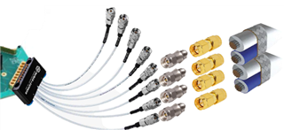
in the DS250DF230EVM datasheet the HUBER+SUHNER MXP breakout cable assembly is recommended to be used for connecting signals. In my case I would like to connect some AWG26 signal wires directly to the J46 connector without the breakout wires.

With this I would like to avoid damping when using 4 interfaces (bridging the wires from SMA to SK, just to connect the HUBER+SUHNER MXP breakout harness afterwards for the J45 connector on the board).

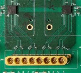
Is there any option to use some connectors going straight to the single pins of the J46 and if, which one can be used for it?

Alternatively, I could connect the AWG26 wires directly to breakout harness by soldering/crimping. But I would like to avoid this option, as this would increase the damping again.


Thanks for your help and kind regards

  • Hi,

    I am not aware of any single connector that would adapt to a single pin of the Huber+Suhner MXP connector.  Can you help clarify what you are referring to by "damping"?  Without knowing further details about your use case, I would suspect that connecting 26AWG wires to our EVM would offer poor signal integrity.  Perhaps you could provide more details about your use case?

    The Huber+Suhner MXP40 series is designed to offer 40 GHz of bandwidth, which is one of the reasons we use this connector on our EVM.  We have found that it offers good signal integrity and reliable, repeatable high speed connections.

    Thanks,

    Drew

  • Hallo Drew,
    with damping I mean the damping coming from many interconnections.
    In my case I work on the transmission of a high data rate (maximum specified for the protocol, or - if possible - above it).

    As we want to max out the distance, I am searching for the setup with fewest connections possible. That´s why I want to avoid coming from my parallel pair AWG26 wire, connect it with SMA connectors, just to connect the SK. Afterward going with the breakout harness on the board connector.

    At the following picture you could see all these connections:

    Because we are at limit of the specification, we need to have the "best" setup possible to max out the distance, where it is still possible to detect the eyes in the eye diagram. That´s the reason why I would like to connect the wires directly pin-by-pin onto the board or at least with as few connections as possible.

    Many thanks

    Lars

  • Hi Lars,

    I apologize if I'm missing something obvious, but it seems like your connectors all consist of SMA or 2.92mm connectors.  These are intermateable with each other, so I wouldn't expect any conversions to be necessary unless you need to convert between male/female connector.  Please let me know if I'm misunderstanding something.

    Regarding "damping", I haven't heard this mentioned before in the context of high speed signal conditioning.  Typically I hear about return loss and insertion loss.  These are definitely a concern, and transmitting a signal through a lot of connectors can cause signal integrity issues.

    You are of course welcome to de-solder the MXP connector from our EVM and solder 26 AWG wire, but I would not have a lot of confidence in the high speed performance of this connection until it had been tested.

    If you require a custom connector, perhaps you could also ask Huber+Suhner to see if it's possible for them to make an MXP40 cable assembly with your connector of choice.

    Thanks,
    Drew

  • Hi Drew,


    thanks for your answer.

    No, you didn't misunderstand anything. The question was how to come from the signal wires to the breakout harness (or even directly to the connector on the EVM board). The “issue” is just to find a connector that can be put on our signal wires without any second/third conversion, bevor connecting the HUBER+Suhner harness. As I did not find any direct connector from the signal wires to the H+S harness, I added the Male/female conversion in-between.

    Maybe I used the wrong wording, when talking about losses. Thanks for correcting. I hope, now it is clear what I thought with it.

    Connecting the wires directly to the board with removing the MXP connector on the EVM was not my intention. In the real application we will also need some interconnection. Using at least one connection will be closer to the real setup.

    If not finding a good solution when talking to H+S, it is also possible to connect our wires to the harness by solder the wires together. The losses of a soldered connection should have almost the same losses as an additional interconnection, right?

    Or do you have a different opinion on this?


     Thank you.

    BR,

    Lars

  • Hi Lars,

    To preface this, I would not consider myself an "expert" in the field of high speed cables and interconnects, so if you or your team has an expert, please feel free to defer to them.  With that said, based on my experience working with high speed signals, I've found that the connectors play a critical role in signal integrity and that at speeds around 25 Gbps, connector selection is very important.

    When it comes to the possibility of soldering wires to the harness, I worry about maintaining the characteristic impedance of the transmission line as well as the high speed performance.  Typically, high speed cables and connectors are designed to have a characteristic impedance of around 50 Ohm.  I would be worried that soldering wires to the harness might result in a vastly different characteristic impedance.  This could lead to reflections.  In terms of insertion loss, I think this is largely impacted by the dielectric material surrounding a conductor.

    In general, at speeds around 25 Gbps, I would be concerned about manufacturing my own cables through splicing/soldering them.  I'm sure that given the right equipment/quality control that this is possible, but it seems very challenging.  I could be mistaken, but I think that in most cases, for a 25 Gbps signal, you will see better signal integrity using connectors/adaptors manufactured for this speed compared to making your own high speed channel.

    Thanks,

    Drew