This thread has been locked.

If you have a related question, please click the "Ask a related question" button in the top right corner. The newly created question will be automatically linked to this question.

DS280MB810: Redriver does not configure from EEPROM.

Part Number: DS280MB810
Other Parts Discussed in Thread: SIGCONARCHITECT, DS560MB410

Hello TI technical folks,

I'm using the DS280MB810 in the following I2C bus architecture:

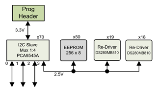
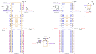
with the following schematics:


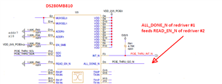
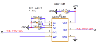
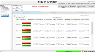
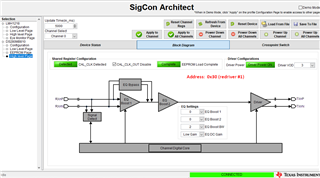
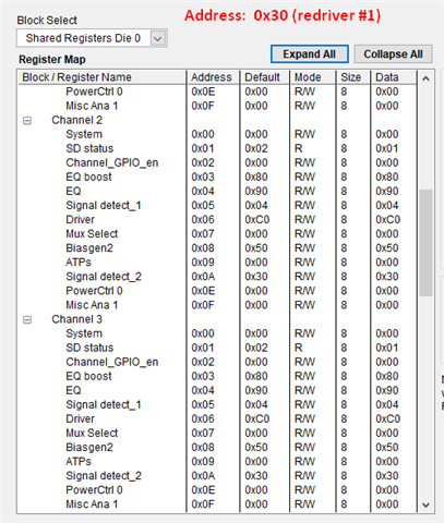
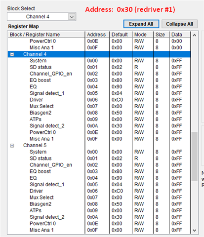
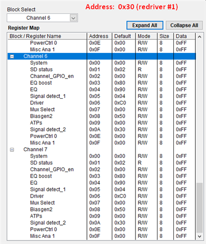
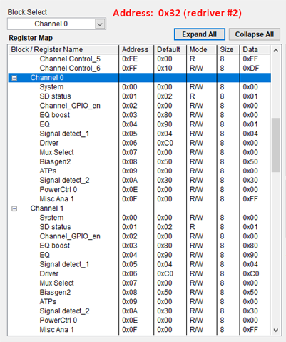
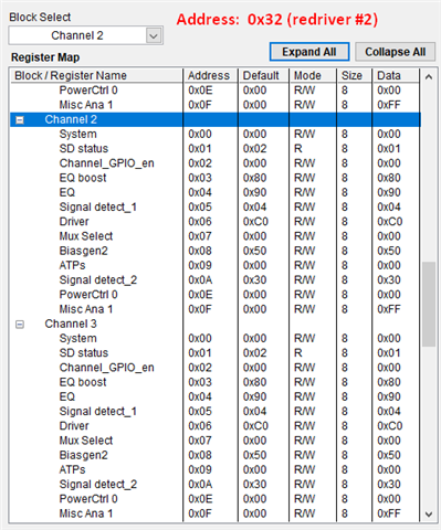
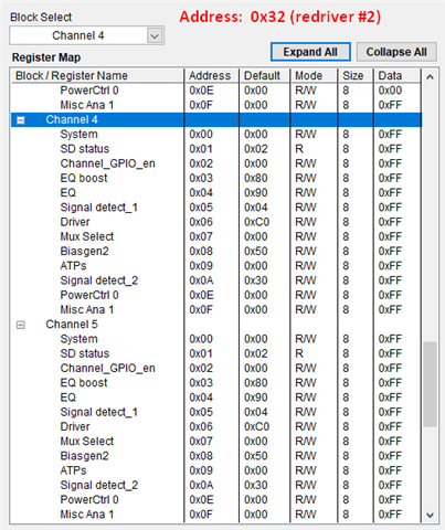
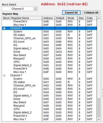
I've programmed the EEPROM with the .hex file appended beow and read back it's contents to verify that it was correctly programmed. Upon applying the D2V5 power, I am able to communicate with the redriver over I2C, but it doesn't appear that the redriver configured itself from EEPROM correctly (or even at all). Specifically, when I probe the ALL_DONE_N pin on redriver #2 it measures 2.5V, meaning that it hasn't finished configuring from EEPROM. Moreover, when I read the contents of the redriver registers over I2C from SigCon Architect, the desired EEPROM values are not present.

I replaced resistor R40 with a zero-ohm resistor, thinking that perhaps a hard-ground was needed at the READ_EN_N of redriver #1, rather than a 1K PD. But, that did not change the behavior and ALL_DONE_N still measures 2.5V at redriver #2. I've also scoured the .hex file contents against what application report SNLA244 says it should contain, and it looks correct. Basically, I set up all channels with these parameter values: VOD=2, EQ1=5, EQ2=0, Boost=3. And the .hex file seems to contain the correct data values for those parameters.

I'm stuck at the moment and looking for hints at what may be going on. Thanks.

Regards,

-Mark

----------------------------------------------------------

.hex file contents:

:20000000D10010E413E413E413E413D555D555D555D555C580100000000000000000000026
:200020000000000000000000000000000000000000000000000000000000000000000000C0
:20004000000000000000000000000000000000000000000000C5801000000000000000004B
:20006000000000000000000000000000000000000000000000000000000000000000000080
:20008000000000000000000000000000000000000000000000000000000000000000000060
:2000A000000000000000000000000000000000000000000000000000000000000000000040
:2000C000000000000000000000000000000000000000000000000000000000000000000020
:2000E0000000000000000000000000000000000000000000000000000000000000000003FD
:00000001FF

  • Hi Mark,

    I have some questions to help with debugging your issue.

    Are the registers of redriver #1 getting set correctly? Is the ALL_DONE_N pin of redriver #1 getting pulled low? How are the address pins configured on redriver #2?

    I looked over your hex file and don't immediately see any issues. I loaded it with SigCon Architect and it set the correct parameter values as expected. Did you generate this file using SigCon?

    Best,

    Lucas

  • Hi Lucas,

    Below is the full schematic page showing redriver #1, redriver #2, and EEPROM. Note that redriver #1 has address 0x18 (7-bit). Redriver #2 has address 0x19.

    No, the registers of redriver #1 aren't set per the EEPROM settings and its ALL_DONE_N pin is still HIGH at 2.5V. It is interesting however that SigConArchitect (SCA) on the Block Diagram tab shows Green for the 'EEPROM Load Complete' status indicator. Those two facts seem to conflict, but I'm not sure what SCA uses to determine that EEPROM load was successful.

    Also shown below are 4 screenshots from SCA, the first two for redriver #1 at 0x30, the second two for redriver #2 at 0x32. Notice that redriver #1 shows all green, while redriver #2 shows pretty much all red. Not sure what that means.

    Let me know if you need further data. Thanks.

    Regards,

    -Mark


  • Hi Mark,

    Have you included a 2k-5k pull up resistor on the SDA and SCL lines? I don't see these on your schematic, and they are required for I2C read/write operations.

    Can you share a screenshot of the channel register values on the low level page for redriver #1?

    Did you generate the hex file using the EEPROM page on SigCon Architect or did you write it manually? I noticed it's changing the value of some reserved registers, which I wouldn't be concerned about if the file was generated from SCA.

    Best,

    Lucas

  • Hi Lucas,

    Yes, we have 4.7K PUs on both SDA and SCL. They are on different page of schematics, but they are there. EEPROMs live on the same I2C bus per above drawing, and they can be read/written fine, so PUs are working.

    Screenshots of the low-level page channel registers are shown below.

    Yes, I used SCA to generate the EEPROM .hex file. Aardvark 'Flash Center' application was used to program the EEPROM.

    Regards,

    -Mark

  • Hi Mark,

    I'm going to try reproducing your issue in lab tomorrow and I'll let you know what I find.

    Best,

    Lucas

  • Hi Mark,

    Unfortunately I ran into some issues while trying to setup my test, but I did find a potential SigCon EEPROM page bug from looking more closely at your hex file. The channel register data, which starts with byte "C5," should be placed after the address map header portion of the file. In your file, this begins on byte 0x13, which would come directly after the address map header portion if each header were 1 byte. However, each address map header is 2 bytes long, so the channel register data should begin on byte 0x23.

    I've written a new hex file with the same channel register configuration as your file, but moved to the correct place within the file. Can you try using this file and let me know if it works?

    https://e2e.ti.com/cfs-file/__key/communityserver-discussions-components-files/138/test.hex

    Note that this configuration sets  VOD=2, EQ1=5, EQ2=0, Boost=3 in registers 0x3, 0x4, 0x6 and sets the rest of the channel registers to 00. If you would like to leave default values in the other registers, let me know and I can write another hex file for this.

    Best,

    Lucas

  • Hi Lucas,

    The programming of EEPROM went fine and I confirmed that contents were per the 'test.hex' file.

    Unfortunately, after power-cycle, the state of the redriver registers is unchanged from before. And the ALL_DONE_N signal still remains at 2.5V (logic HI).

    I will work this problem starting again on Monday and have some ideas on my side. Look forward to any other insights you may have. Thanks for your continuing efforts. 

    Regards,

    -Mark

  • Hi Mark,

    I will continue trying to replicate your issue and will get back to you with my findings later this week.

    Best,

    Lucas

  • Hi Lucas,

    To review what is happening in my setup..

    Redriver #1 is in I2C master mode upon power-on, and then (we believe) it attempts to read EEPROM, but fails for some reason. We know this because it never drives the ALL_DONE_N output low (as measured with the DVM) and the redriver register values are still the default (not the EEPROM) values. But, redriver #1 does transition from I2C master to become I2C slave. I know this because I can write a new register value and read it back over I2C. Therefore, redriver #1 "kinda" completes its power-on task of transitioning to I2C slave, but it fails the EEPROM task.

    Furthermore, because redriver #1 ALL_DONE_N never drives low, redriver #2 never even initiates trying to read from EEPROM. I know this because I can't write a register with a new value and then read it back -- the write of the new value never "takes". This tells us that redriver #2 is still in I2C master mode, not slave mode. It's stuck.

    Because of the above behavior, I really wonder if the .hex file is still messed up somehow and redriver #1 doesn't complete configuration from EEPROM correctly for that reason (I don't know what other reason there could be that it doesn't successfully configure).

    Do you have a .hex file that is used on the evaluation board that I can simply try on my setup? I'd like to program a "known good" .hex file into the EEPROM to confirm that I can get that to work. But, make sure it's "known good" by testing it on an eval board before you send it to me. Thanks.

    Regards,

    -Mark

  • Hi Mark,

    Thanks for summarizing everything, I'm actively working on replicating your issue in lab. I will try writing and testing a hex file that works so I can send it to you by the end of this week.

    Best,

    Lucas

  • Hi Lucas,

    Note, I accidentally clicked the Resolved Issue button, I do not consider this issue resolved yet.

    Another thing to ask.. Please provide a couple specific EEPROMs part-numbers that are known good and that work on the DS280MB810 EVM. The BOM for the EVM does not call out a specific EEPROM, but has a socket. Therefore, please let me know what specific EEPROM you have socketed on the EVM that you're testing with.

    I want to fall back to proven EEPROMs and a proven .hex file. If you can provide those today or tomorrow that would be excellent. Thanks.

    Regards,

    -Mark

  • Hi Mark,

    Unfortunately I'm running into some unexpected challenges with testing EEPROM programming on DS280MB810. I'm using the 24FC16 EEPROM, but I haven't gotten it working properly with the redriver yet. Unfortunately it's going to take more time to resolve your issue, but I'm hopeful I can provide more feedback next week.

    Best,

    Lucas

  • Hi Lucas,

    Are you having problems programming the EEPROM itself, or with the DS280MB810 configuring from the EEPROM? I assume it's with the redriver configuring from the EEPROM, but just want to confirm. Since SigConArchitect doesn't allow direct programming of the EEPROM, I currently use an Aardvark programmer with Flash-CenterGUI application to program my EEPROM.

    Regards,

    -Mark

  • Hi Mark,

    I'm running into issues with configuring the DS280MB810 from the EEPROM. I'm also programming the EEPROM using an aardvark with flash center and haven't had any issues with this.

    Best,

    Lucas

  • Hi Lucas,

    Anything new on the configure from EEPROM issue we are seeing.

    Regards,

    -Mark

  • Hi Mark,

    Apologies for the delay on this.  We're continuing to look into this, hoping to have resolution this week.

    Thanks,

    Drew

  • Hi Mark,

    Thanks for your patience. I observed that if I disable CRC, the EEPROM seems to load correctly.  To continue your evaluation, I would recommend doing this for now. I'm looking into why the device is not accepting the CRC generated by SigCon architect and am hoping to have an explanation within the next week.

    Thanks,

    Drew

  • Hi Drew,

    Thanks for the disable CRC hint. I have not had opportunity to try that yet, but will.

    In the meantime, I have another rather important question regarding the MUXSEL[1:0] pin-mode. Can pin-mode be enabled via EEPROM configuration or is an I2C register write (to shared reg 0x05[1]) required to place device in pin-mode?

    Specifically, Tables 11 and 12 in SNLA244 seem to indicate that only shared register 0x05[2] can be set during EEPROM config. However, to enable pin-mode, shared register 0x05[1] would need to be settable during EEPROM config as well, but the tables seem to indicate it cannot be set. Moreover, the default for shared reg 0x05[1] is 0, meaning that pin-mode is disabled by default. All this seems to lead to conclusion that pin-mode can only be enabled via an I2C register write to bit 1 of shared register 0x05. Can you confirm, or otherwise point me to another bit somewhere in the EEPROM that would enable pin-mode? Thanks.

    If I2C write is required to place device in pin-mode, then EEPROM configuration is likely a moot question for us, as we need pin-mode.

    Regards,

    -Mark

  • Hi Mark,

    Your observation is correct, MUX pin control can only be enabled through an I2C write on DS280MB810.  If pin-mode is required for your application, you will need an I2C write to configure this.  We improved this on our newer DS560MB410 part by having MUX_CONFIG_PIN_CTRL as 1 by default, but unfortunately, I am not aware of any work around on DS280MB810.

    Thanks,

    Drew