This thread has been locked.

If you have a related question, please click the "Ask a related question" button in the top right corner. The newly created question will be automatically linked to this question.

AM26LV31E: AM26LV32E - Design help

Genius 17525 points
Part Number: AM26LV31E

Hi Experts,

Seeking assistance for designing the AM26LV32EIDR:

Seems there is no EVM for this part.

Is the schematic structure given in the picture below correct?

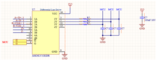
Following questions have been raised:

  1. Should I add the terminating resistor between lines A and B?
  2. Should I add it between the entire A and B line?
  3. What should be the value of the terminating resistor?
  4. What should be the R and C values in the schematic?
  5. Is there anything else I should add to the schematic?

Thank you.

Regards,
Archie A.  

  • Hi Archie,

    You are using the 32 in the design (the receiver) correct?  

    If it is the "32"  (the receiver) as indicated in schematic and not the "31" as indicated by post title please see below:

    1. If it is the terminal node in the system it should be terminated - i.e. the last receiver on the multi-drop bus it should be terminated with a 100 Ohm resistor (RS-422 standard as this is an RS422 device) 

    2. If added placing the termination resistor from A to B close to the A/B pins  is the best bet to minimize potential impedance discontinuities.

    3. 100 Ohms - RS422 standard; it can be more but no less. 

    4. Depends on application - they don't need anything to output; so it depends on the needs of application and MCU input pins - its not uncommon to have a cap to ground and the pin to be pulled to VCC if using the device with UART data - the series resistor may or may not be there. But ultimately it depends on use case. Generally when I do similar board designs every MCU facing output would have a 0 Ohm series resistor between pin and jumper, pull up resistor and a cap to ground - the values of which greatly depend on application needs.

    5. Pull up 4A to VCC and 4B to GND to prevent oscillations at the unused output. If anything else maybe consider passive failsafe resistors to help increase noise immunity of the device - https://www.ti.com/lit/an/slyt324/slyt324.pdf - it states 120 ohms for the termination because its based around RS-485 - but a similar process can be used - the difference is there is only 1 termination resistor and its nominal value is 100 Ohms - (rs-485 has 2 120 Ohms in parallel). 

    If you are looking for a review of the driver version (31) than please let me know - and if needed upload the '31' schematic snippet. If this isn't needed than no worries!

    Please let me know if you have any other questions. 

    Best,

    Parker Dodson