Hello,
Having an issue getting this PHY operating in RMII mode when strapped for Basic Mode.

Seeing 50MHz on REF_CLK.
The activity LED is working fine but the speed LED is off (100M?).
Any help would be appreciated.
This thread has been locked.
If you have a related question, please click the "Ask a related question" button in the top right corner. The newly created question will be automatically linked to this question.
Hello,
Having an issue getting this PHY operating in RMII mode when strapped for Basic Mode.

Seeing 50MHz on REF_CLK.
The activity LED is working fine but the speed LED is off (100M?).
Any help would be appreciated.
Hi Jacques,
I would like to ask couple questions for further debug:
--
Thank you,
Hillman Lin
Hello Hillman,
The PHY is strapped as shown in the image. To my knowledge, it is set up for RMII operation.
The PHY is connected to an STM32 consequently, I cannot read any registers.
We had this working with a MicroChip LAN8742A-CZ but we designed in the TI part due to availability issues.
Regards.
Hi Jacques,
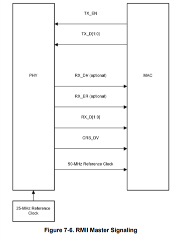
I would like to double check rather your PHY is strapped in RMII master. In RMII communication, it required PHY to be master use the 25MHz in XI pin and provide 50MHz to the MAC which is STM32 in your case. STC32 should read 50MHz clock signal coming from PHY which is shown in the figure below:

If possible, reading register would help us on further debug the health condition for your DP83826 PHY remotely.
Hope this information help with your question.
--
Regards,
Hillman Lin
Hello Hillman,
We checked our STM code and it requires the PHY to be at address 0x00.
Given that we have to make modifications to the assembly, we decided to switch it over to Enhanced mode as the default address is 0x00.
Straps 6 and 8 are now the ones that are connected high.

We have done these changes and we now have communication!
The only thing that is not working as we would like is the speed LED (LED1).
We have Strap 6 pulled high to make it LED1 but the logic is reversed.
Table 6-1 states that the polarity can be reversed by placing a pull-up or pull-down on Strap 1.
This cannot be true given that we need to keep Strap 1 high in order to be in RMII mode.
Is there another strapping option to reverse the logic?
Hi Jacques,
Glad to hear that it works out for the communication :)
Regarding to reverse polarity for LED1, we normally implement based it like the figure below:

Since the LED_1 pin is pull up internally with fixed active low, the right figure would be recommended for the schematic.
--
Regards,
Hillman Lin