This thread has been locked.

If you have a related question, please click the "Ask a related question" button in the top right corner. The newly created question will be automatically linked to this question.

AM26C32: Fail-safe pull-up/down Resistance value and Internal resistance error

Part Number: AM26C32
Other Parts Discussed in Thread: SN65HVD1780-Q1

Hi, Staff

Q1:
If Vic of AM26C32 is 0V to 5V, will VIT+/- operate without problems if it is ±0.1V?

The datasheet says VIT+/- is ±0.2V when Vic is ±7V.

When calculating Fais-safe pull-up and pull-down resistors,
The resistance value differs depending on whether VIT+/- is ±0.1V or more or ±0.2V or more.
Which one should I use?

I understand that the pull-up and pull-down resistor values change depending on the Vic value of the application.

Q2:
8.2 EQUIPMENT OF A OR B INPUT
What is the % error between 17kΩ and 288kΩ inside the device?

best regards

cafain

  • 1.VIC is the range of input voltages. If you can guarantee that the bus voltages never exceed the narrower range, then you can use the values for ±0.1 V. But note that RS-422 drivers guarantee a differential voltage of more than ±2.0 V; designing for less than this will remove the noise margin.

    2. Calling these values "nominal" implies that nobody bothered to measure guaranteed limits or even typical values.

  • Hi Cafain,

    1. Clemens is correct - if the input voltage stays within the narrow range of 0V to 5.5V than the thresholds will be -0.1V and 0.1V respectively. However if the full range of potential input values are needed than the value will be +/-0.2V. If adding passive fail-safe resistors I'd design for +/-0.2V as that will cover the entire possible use case range - and if the thresholds are closer to +/-0.1V during operation then you just added a bit of additional noise margin which is generally beneficial to the system. 

    2. Don't worry about the eq. circuit - its not all that helpful from the design point of view. These eq. circuit diagrams aren't included as much in newer devices because they add details that aren't all that helpful. The input resistance should be assumed to be 12K and that's the value that needs to be designed for as it is the minimum input resistance that can be seen. 

    In general you should be designing around the specs in the electrical characteristics table, and if a max/min is used that should be the design value as typical isn't a boundary condition and the system will most likely not be typical values for all use cases. For input resistance for RS-422 or RS-485 devices the minimum resistance should be used for passive fail-safe resistors as if you set the impedance too high it may not accurately reflect the max potential loading from the IC. For passive failsafe resistors its common practice to replace the input into an RS-422/485 with a resistor to ground for the design process of sizing the passive fail safes. 

    Please let me know if you have any other questions and I will see what I can do!

    Best,

    Parker Dodson

  • HI, Staff

    let me check again

    Q1.
    When designing a passive fail-safe circuit, is it okay to think that it can be designed without considering the tolerance of the 288kΩ pull-up/pull-down resistor inside the AM26C32IPWR?
    Should I consider the input resistance 12kΩ (min)?

    Q2.
    Regarding the calculation of the pull-up/pull-down resistance, since 200mV or more is required between the A and B terminals,
    Is it OK to simply determine the resistance value by the following formula?
    ex)
    Vcc=5V, Rt=120Ω, R1=pull-up, R2=pull-down

    R1=R2=RVIA-VIB > 200mV
    VIA-VIB= RT(Vcc/(2R+RT) → 200mV

    From this formula R1=R2=1.44kΩ

    Q3.
    When connecting 10Ω in series to the Pulse-Proof Thick-Film Resistor for the A terminal and B terminal, how do you calculate the resistance value of this 10Ω?

    For example, SN65HVD1780-Q1 Figure 17 is used as a reference.

    best regards

    cafain

  • Hi Cafain,

    1. Consider input impedance to be 12K - in reality it will most likely be higher - but if you design the input impedance too high you could potentially overload the bus - so 12K is the safest value for this device.

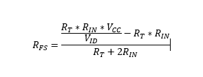
    2.Yes that is proper reasoning - for simplicity the formula is as follows:

    R_FS - failsafe resistor pull-up or pull down (assuming they are equal)

    R_IN  = 12K input impedance minimum for 1 node - each additional node will reduce the input impedance

    R_T = termination resistance - since this is a RS-422 device the maximum loading impedance between differential inputs is 100 Ohms - any impedance < than 100 Ohms could attenuate the signal or worst case overload the bus. Using 120 ohms is fine. 

    VID  - the input idle voltage (200mV for this device)

    Assuming pull up is to VCC.

    So your calculated value seems to make sense for 1 node - but the entire system needs to be considered - so for point to point Rin will be 6K instead of 12K since there are 2 nodes on the line. and the impedance drops to about 1420 instead of 1440 - so not a huge difference but as more nodes are added the input impedance will have a much larger effect on the bias. 

    3. Its a standard practice that we have also tested. In general the series resistor is there to increase the RC time constant of the bus so fast transient events can potentially be mitigated. However we don't want to attenuate our data signal that much so in practice 10 Ohms is used. A thick film or wire wound is the suggested type of resistor. Through testing customers may deviate from the 10 Ohms - but it should be a lower value. 

    Please let me know if you have any other questions!

    Best,

    Parker Dodson