This thread has been locked.

If you have a related question, please click the "Ask a related question" button in the top right corner. The newly created question will be automatically linked to this question.

DS90UB941AS-Q1: Application problems of chips

Part Number: DS90UB941AS-Q1
Other Parts Discussed in Thread: USB2ANY

We are currently debugging TI's serializer 941+deserializer 948 on the 8155 platform, but we have encountered some problems.

The specific problems are as follows:

At present, the serializer 941 can read and write registers normally, and the deserializer 948 device has appeared, which can also read and write I2C,

By checking the 948 register 0x1C, the serializer and deserializer have been locked.

The mipi clock of the platform is set to continuous mode, so the mipi clock has always been in hs mode, but the lvds screen at the 948 end of the screen has no content display.

Therefore, we request your technical support and ask some questions:

1. If there is a test mode, you can directly brush the screen to verify whether there is no problem with our hardware

2. The mipi of the platform is output to 941, and then to 948948 through FPD LINK to analyze the data, and finally to the lvds screen. Does this process necessarily require that the mipi of the platform must be

Hs clock, if mipi clock can be in continuous mode or non-continuous mode, do you need to set some registers of 948, and then let 948 solve continuous mode or non-continuous mode

3. The register manual we got is in English, which is obscure and difficult to understand. Many registers are not very clear. Is there any register manual or some data in Chinese, and the code annotation is easy to understand

If so, can you provide it for us to check

  • Hi Tonyx,

    941 and 948 have pattern generation to individually verify OLDI to display, then Ser to Des to display video paths.

    If you are able to hook a USB2ANY or Aardvark to the I2C bus of SER or DES, then it might make debugging easier through the graphical interface instead of scripting.

    Yes, 941 DSI input must be continuous CLK mode since 941 used input CLK to generate the clocking sent on FPD-Link. 

    Here is a detailed debug guide for 941 and DSI: https://www.ti.com/lit/pdf/snla356

    Regards,

    Logan

  • Our hardware connection is

    SOC output mipi waveform 941 serializer έ FD_ LINK 948 deserializer lvds screen


    At present, our progress is:


    There is no problem with the output mipi waveform of the SOC, because we have a switch switch, which can be connected to the hardware above, or the SOC can be directly connected to a mipi screen,

    The mipi screen can be displayed normally. The mipi signal is a discontinuous signal. It can be switched between LP and HS because I looked at the register

    The manual can set the mode to non-continuous or continuous mode, indicating that there is no problem with mipi signal


    We adopt the brush mode, which can control the register of 941 to directly brush the lvds. The screen switches between green, purple, black, white and progressive colors

    It shows that the hardware of our 941 948 lvds screen is OK.


    Now there is only 941 serializer "FD" left_ LINK 948 deserializer. The register of this part needs to be set. If you have technical support, please help me to look at it

    How to set the register? I have a general look at the registers. Most of them can be understood, but some registers cannot be understood. Some slight differences may be

    The screen is not bright, so please help me

  • Hi Tonyx, 

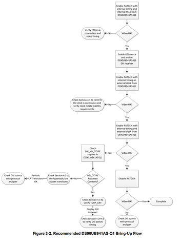
    Did you review the 941 DSI bring-up guide I previously attached? Can you clarify where in the flow diagram below you are failing? 

    Please provide the following information:

    • PCLK being used
    • DSI configuration: 
      • CLK mode
      • Burst mode, non-burst mode with sync events, non-burst mode with sync pulses
    • 941 Clock mode being used (DSI reference clock mode, external reference clock mode, internal reference clock mode)
      • If DSI CLK mode is being used (no external REFCLK used) then DSI CLK MUST be in continuous mode
    • Can you provide current scripts?
    • Provide oscilloscope waveform of DSI CLK and DSI data signal to observe when it is entering LP11 mode
    • Schematic of 941
    We adopt the brush mode, which can control the register of 941 to directly brush the lvds. The screen switches between green, purple, black, white and progressive colors

    What is brush mode? Are you using 941 Pattern Generation in this case? Does this use internal timing, or rely on external clock? 

    Regards, 

    Logan