This thread has been locked.

If you have a related question, please click the "Ask a related question" button in the top right corner. The newly created question will be automatically linked to this question.

TCAN1057AV-Q1: Common mode choke value

Part Number: TCAN1057AV-Q1

Hello team,

I am planning to use Common mode choke for the CAN TCAN1057AV signal and it was suggested by one the teammate to use 100uH choke.

Please can you explain how to select the value of the Common mode choke and why it is 100uH in most of the  design. It will helpfull if you could provide the Answer as early as possible

Thank you
  • Hi Darshan,

    This is a fairly complex topic, so I will link an app note that will go over things in more detail. In short, the 51µH - 100µH range is a high enough to have a positive effect on the CAN signal by filtering out common mode noise while being low enough to not heavily impact the CAN data itself or contribute negatively to transient behaviors through inductive kickback.This range is pretty standard throughout the industry as it has consistently offered favorable results for both EMC testing as well as allowing for good system-level transient immunity.

    Common Mode Chokes in CAN Networks: Source of Unexpected Transients

    Let me know if you have any more questions. 

    Regards, 
    Eric Schott 

  • Hello Eric thanks for the answer,

    I have one more question it will be helpfull if you could make me to understand 

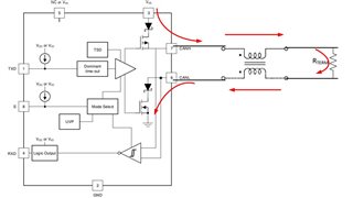
    As you said Common mode choke will allow differential signal to pass through it , since current flow in differential signal is opposite to each other.

    I am really facing difficulty in understanding how current flow in CANH and  CANL  line will be in opposite direction . 

  • Hi Darshan,

    The CAN driver works by sourcing current on the CANH pin and sinking current on CANL. This current flows through the termination resistors external to the transceiver to create the differential signal. Because the CMC is nominally placed between the transceiver and the termination resistance, the current will flow in opposate directions through the CMC coils. This is different from any common mode current which would flow in the same direction through both coils from the bus side to the transceiver side (or vice versa). This common mode current is what the CMC resists so it acts to reject it as common mode noise. 

    Let me know if this is clear or if there's anything else I can elaborate on. 

    Regards,
    Eric Schott 

  • Hello Eric

    Thanks for the solution,

    We have BCI  failures in CAN bus line  at 40 mA , Please can suggest a common procedure need to follow in order to over come BCI failures in CAN transcivers 

    Would be much helpfull to Pass the  EMC test

  • Hi Darshan,

    Do you know what test standard is being used for the BCI testing? We have our devices evaluated for J2962 BCI testing which requires no CAN errors at a level between 31mA and 200mA depending on frequency. I would be interested to know what frequency you are seeing the failure at. 

    BCI behavior is typically dependant on many factors of the system setup including board layout, routing, passive component population and placement, and transceiver. Adding/switching common mode chokes are a common method of improving a system's BCI performance. I have seen good results with the act45b-510-2p model of CMC. 

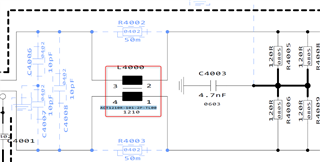
    Are there other component placement options on the bus-side of the CMC in the schematic? I notice there are capacitor placement options on the IC-side of the CMC. Are these populated for the BCI testing? 

    Regards,
    Eric Schott 

  • Hello Eric ,

    sorry for the late reply ,

    we have failures at 280 MHz  - 370MHz with a threshold of 30mA .

    if possible please can you explain me how BCI is going to disturb the circuit interms of Noise and How we have to take care  of it 

    I have seen in some cases adding Capaciotr will improve the BCI - can you explain about this

  • Hi Darshan,

    I'm sorry to hear you are having failures here. 

    Can you share a bit more about your test requirement? Is there a frequency vs level plot showing what mA value is required for each frequency range? What is the distance between the coupler and DUT?

    BCI causes communication failure by moving the CAN signal outside of the operational range of the CAN receiver for long enough that the system misses a bit. To prevent this communication failure, the energy introduced to the CAN transceiver from the CAN bus can be reduced using external passive components. The most common passives to help BCI performance are common mode chokes, TVS diodes, and bus capacitors. We've already discussed the use of CMCs a bit in this post. TVS diodes help shunt some of the BCI current to ground away from the receiver. If you do not yet have a TVS available, I would recommend the ESD2CAN24. Lastly, bus capacitors can be used to filter out the high frequency energy from BCI and will likely make a difference here given the high frequency failure. Bus capacitor values typically range between 10pF and 150pF depending on the size of the system. 

    I would also like to mention that we have test results from a third party showing TCAN1057A passing BCI in this range above 100mA, so I don't think what we're seeing here is a weakness on the transceiver side. Hopefully with some additional passives the test results will improve for this system. 

    Keep me updated on the testing progress and let me know if you have any questions in the meantime.

    Regards, 
    Eric Schott