Part Number: TCA9548A
Other Parts Discussed in Thread: INA219, TCA9803
hi there,
We are designing I2C bus for system. MCU (STM32) is the mater,, slave devices as below. All IC powered by 3.3V. Total I2C pcb trace length might be 80cm..
Since there is no address-conflict issue, seems we can just connect all slave devices on ONE I2C bus ( take two MCU's pins). Still not sure how to determine if a switch(TCA9548A ) or I2C buffer should be used?
Could you please give some advice?
[ Slave deivce]
INA219, 2pcs, power monitoring
ADS7830IPWR, 4pcs, voltage monitoring
TCA9546APWR, 1pcs. managing two identical battery package.
LM95214CISD, 3pcs, temp sensor
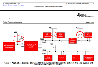
Another question is, in application note slva689 , there are three pairs of pull-up resistors before and after the I2C switch and buffer . But I think those resistors are parallel if the path 0 is enabled, so the first pair of resistors should be enough? Thanks!