This thread has been locked.

If you have a related question, please click the "Ask a related question" button in the top right corner. The newly created question will be automatically linked to this question.

DS110DF1610: How to generate the correct hex file

Part Number: DS110DF1610
Other Parts Discussed in Thread: USB2ANY, DS110DF410

HI,TI

1. How to generate the correct hex file?

When using retimer DS110DF1610, select EEPROM as the startup configuration mode, and have the target board (non DEMO board) and EEPROM chip Programming tools on hand. Now I want to generate a ". HEX" file in the "EEPROM page" of SigCon Architect, then burn it directly into the EEPROM chip, and configure the retimer to read the internal data of the EEPROM in the SMBUS master mode for itself work configuration. However, the data on the "EEPROM page" page of SigCon Architect cannot be updated. The EEPROM data generated by clicking the "Write to EEPROM Hex" button are all “00”, and the software is now in DEMO MODE . What is the problem? How to generate the correct hex file? Can you provide a generic hex file for reference?
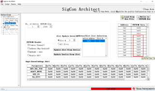
  

 The generated hex file data is 00:  
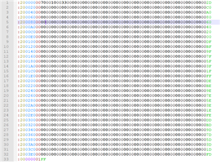
  1. Is the EEPROM size 64kbit (AT24C64) OK?
  2. Is there any rule or good method for debugging RX TX value? Can you share it?

thanks!

Best,

jack

  • Hi Jack,

    1) To generate EEPROM file, please configure the retimer as desired using SigCon Architect.  This can be done in demo mode if it's not possible to connect SigCon architect to the device via USB2ANY.  Once the device is configured, press "Update Slot from Device" on the EEPROM page in order to update the EEPROM data with the device data from SigCon Architect. This file can then be saved.

    2) Looking over the AT24C64, it seems to use 2 word addresses as part of its addressing.  AT24C01C/02C/04C/08C/16C EEPROMs, which this device is known to be compatible with, seem to use 1 word address during addressing. I would recommending using one of these if possible in order to ensure compatibility.

    3) For RX, we generally leverage the internal eye monitor in order to observe if the retimer is equalizing the signal well.  It is good to target a HEO/VEO of at least 0.4 UI and 200 mV.  For TX, this will be more dependent on diagnostics from your link partner.  You can perform a mixture of trial/error and greenbox testing to reach the best TX settings.

    https://www.ti.com/lit/pdf/slyt678

    Thanks,

    Drew

  • hi  Drew,

    Thank you for your answer. For the first question, there are still some questions: Only after the device is configured can a hex file be generated. Currently, there is no USB2ANY data line, so it is not possible to configure the device. Is there any other way to generate a hex file? Can you provide a hex file for reference?

    Thanks,

    jack

  • Hi Jack,

    For most of our devices, we are able to use SigCon architect in demo mode to generate an EEPROM.  It seems like this SigCon Architect profile is not enabling this functionality.  I can provide an EEPROM hex file early next week.  Apologies for the inconvience.

    Thanks,

    Drew

  • hi  drew,

       We look forward to your reply.

    Thanks,

    jack

  • Hi Jack,

    I am still planning on providing an EEPROM early this week.  Thanks for your patience.

    Thanks,

    Drew

  • hi  drew,

      ok.Ask for additional questions:

    1. Does the device have initial operating parameters? If the power supply (2.5V), reset, and clock (25MHz) conditions are met, can the chip work normally?
    2. What is the performance of the device after normal operation?
    3. What are the symptoms of equipment malfunction or errors?

    Thanks,

    Jack

  • Hi Jack,

    1) Typically TI's retimers by default will lock to a couple default data rates without additional configuration.  A limitation with the DS110DF1610 is that it supports multiple REFCLK frequencies.  Because the default REFCLK frequency is 125 MHz, I would not expect the device to operate correctly without selecting a 25 MHz REFCLK.

    2) What sort of performance metrics are you interested in?

    3) Symptoms of equipment malfunction might be receiving unexpected I2C communication errors or an inability to acquire CDR lock.

    Thanks,

    Drew

  • hi  drew,

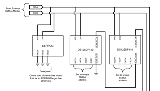
      Did you find the EEPROM file? How to set A0, A1, A2 of EEPROM?

    Thanks,

    Jack

  • Hi Jack,

    Apologies for the delay, I will plan on providing EEPROM file today.  From DS110DF410 datasheet, one or both of A1, A2 should float for EEPROM > 256.

    Thanks,
    Drew

  • Hi Jack,

    Apologies for the delay.  I generated this file by setting the DS110DF1610 to default settings and using SigCon Architect to generate the EEPROM file.  

    Thanks,

    Drew

    ds125df1610-default-w-dut.hex