This thread has been locked.

If you have a related question, please click the "Ask a related question" button in the top right corner. The newly created question will be automatically linked to this question.

SN65HVD230: SN65HVD230

Part Number: SN65HVD230

Hi, everyone.

I have the next problem with SN65HVD230 CAN working, but when I check the signal on the oscilloscope for example only TX, I see strange signals.
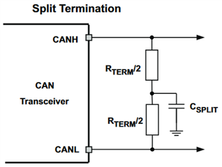
Photo below split connection:
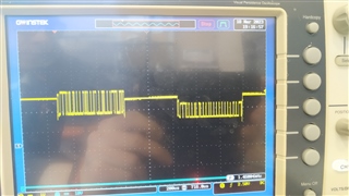
Standard connection:
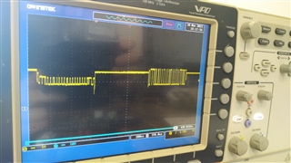
Schemes were different. i tried different values for resistors and capacitors, and the result looks the same.
Sorry, i forgot the project on another PC, and the schemes i take from the forum. But they are very similar to the original.
Standard:
SN65HVD230: CAN Physical interface problem - Interface forum - Interface -  TI E2E support forums
On split termination I had Rterm = 60R and Csplit = 4.7nF

With Kind regards,
Oleksii

  • At what point in your unknown schematic did you measure? And did you measure an absolute voltage or the differential bus voltage?

    Why do you think that the waveform is strange?

  • I measured on CANH. 
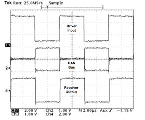
    For example, the CAN bus should bee look like this on the photo (from the datasheet for SN65HVD230):

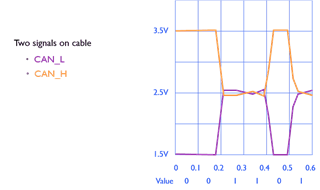
    CAN must have a "zero" voltage level, and CANH should be higher than this level and CANL lower this level:

    In the photo, you see different voltage levels.
    The signal goes from "zero" to both minus and plus.
    The signal on the oscilloscope does not match the documentation.

  • Other transceivers on the bus can affect the voltages, especially that idle voltage, which is only weakly driven.

    The only way to assess the signal quality is to measure the differential voltage.

  • But, I have CAN BUS ANALYZER TOOL(Microchip) and PCAN-USB, and connect to the same equipment with CAN, and the signal looks good.
    As on the datasheet, when I connect my device with SN65HVD230, I have this problem.

  • I see nothing wrong with the waveform. Does you device work?

  • Yes, it's working, but i trying to understand, why, when i connect device with SN65HVD230 i see this signal:
    But when i connect to the same sensor, PCAN-USB, i see this signal:

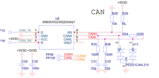
    Real scheme:

    Kind regards,
    Oleksii

  • This is quite different from the schematic shown above.

    What is the purpose of R35 and R36? Try removing them.

  • Had tried, same situation.

  • Thanks for the help over the weekend Clemens!

    The waveform shown here shows two transceivers driving different common modes on the bus. When the 5V node is driving (first frame in the most recent scope shot) the common mode is at 2.5V and the CANH and CANL lines are driven to higher levels during the dominant states. In the second frame, we see the 3.3V transceiver (SN65HVD230 presumably) driving with a different common mode of 1.85V (3.3V / 2). We can see both CANH and CANL being driven to lower dominant-level voltages compared to the 5V frame. This is all expected because of the different supply voltages and does not impact the actual CAN data which only cares about the differential between CANH and CANL. 

    Note on the dominant states during each CAN frame that appear different from all of the other dominant bits; this is the ACK bit where multiple transceivers may be driving dominant at the same time. Therefore, the bus level is some average of the transceivers' dominant drive levels. Again the different here is all the receivers care about, so this is no issue. 

    Let me know if this is all clear and if you have any more questions. 

    Regards, 
    Eric Schott