This thread has been locked.

If you have a related question, please click the "Ask a related question" button in the top right corner. The newly created question will be automatically linked to this question.

DP83869HM: Phy not responding after re-programming FPGA

Part Number: DP83869HM

Hi,

Our board contains a FPGA and a DP83869HM PHY with SFP (RGMII to 1000Base-X).
On start-up, the PHY starts always OK. But after re-programming the FPGA, sometimes the PHY doesn't respond to the SMI bus. 
On a MDIO read, I get always the same data (first data is random, all next data is the same as the first). It seems the PHY is frozen.
Only a power-cycle helps. The XI clock and Reset signal comes out the FPGA (hard-coded, not controllable) with a pull-down resistor. 

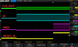
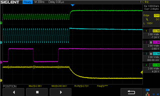
Some timing measurements:
- The XI clock is started 17ms before rising edge of HW_RESET.
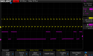
- The MDC clock is continuously, started 34us after HW_RESET. The frequency is 1 MHz.  (The first MDIO action is a long time later).

Thanks in advance,

Jacob 

  • Hi Jacob,

    May be after re-programming is the FPGA holding the PHY in reset ?

    You can try measuring the input clock to the PHY and also the CLK_OUT pin of the PHY, if the clock signal is noticed.

    The XI clock should be provided before the rising of Reset_N, please refer tot he timing diagrams in the datasheet (Section 8.6):
    https://www.ti.com/lit/ds/symlink/dp83869hm.pdf?ts=1679333018695&ref_url=https%253A%252F%252Fwww.ti.com%252Fproduct%252FDP83869HM

    Regards,
    Rahul

  • Hi Rahul,

    See the scope image below. 
    The RESET_N signal is 0.26V while the FPGA is programmed. This is a valid Vil level. (VIO = 2.5V)
    The CLK_OUT signal is always the same as XI, with or without functional SMI bus.


    Startup after programming the FPGA

    Reset sequence initiated by a FPGA reset

    Thanks in advance,
    Jacob

  • Additional info: With functional SMI bus, the CLK_OUT signal stopped after writing register 0x170 (CLK_OUT disabled). 
    With dysfunctional SMI bus, the CLK_OUT is still active because writing 0x170 doesn't work. 

    The probe of CLK_OUT may have been connected incorrectly causing the levels not to be met.

    Thanks in advance,
    Jacob

  • Hi Jacob,

    Thank you for sharing the information, please let review this and update you early next week.

    Regards,
    Rahul

  • Hi Jacob,

    Scope plot image 1:

    Is this plot after programming the FPGA ? I notice that MDC is low, when reset is low, but why isn't clock out low ?

    Regards,
    Rahul

  • Hi Rahul,

    The first 6 ms of the scope plot image, the FPGA is booting. All FPGA pin's are floating. But the CLK_OUT is a output of the PHY, I don't know why he is floating after power-up, until the XI clock input toggles. 

    If you want; I can take a new scope image of the first moment that XI clock toggles. (and I wil also verify that the CLK_OUT signal are good measured)

    Best regards,
    Jacob

  • Hi Jacob,

    Thank you for confirming. My understanding on your issue is that the PHY is functioning before and after the programming of the FPGA (as the CLK_OUT is showing output), but the SMI is not able to be accessed after programming the FPGA (MDC/MDIO bus and register read/write issue).

    Can you check the MDC/ MDIO read/ write operation in the scope or logic analyzer ? and compare it with Figure 9-13 or Figure 9-14 in the datasheet:
    https://www.ti.com/lit/ds/symlink/dp83869hm.pdf?ts=1680285411743&ref_url=https%253A%252F%252Fwww.ti.com%252Fproduct%252FDP83869HM

    Regards,
    Rahul

  • Hi Rahul,

    Here is a recording of the first cycles of a read action. I see no anomaly in the communication.
    Abnormalities in communication I do not expect either, because it is the same FPGA code that always allows communication with the PHY after power-up, but sometimes not after a re-program of the FPGA. A PHY reset does not help then and a power-cycle is needed.

    I cannot tell if the PHY is working because the LEDs are not flashing and no communication is possible.
    To verify this, I will try a test with RGMII to 100Base-FX boot mode because that works without auto-negotiation. 

    Question: Is the SMI state machine reset by the RESET_N input?

    Regard,

    Jacob

  • Hi Jacob,

    I cannot tell if the PHY is working because the LEDs are not flashing and no communication is possible.
    To verify this, I will try a test with RGMII to 100Base-FX boot mode because that works without auto-negotiation. 

    Please share your feedback after the tests are done.

    Question: Is the SMI state machine reset by the RESET_N input?

    RESET_N will reboot everything in the PHY, including the strap configurations.

    Regards,
    Rahul

  • Hi Rahul,

    I placed the PHY in RGMII to 100Base-FX bootmode.
    When the PHY failed, the LED1 and LED2 output are high (the same as in reset or powerdown mode).
    On the fiber output (SO), there is no signal availiable. 
    Switching the RESET_N input has no effect.

    My conclusion is that the PHY is not working. 

    Regards,
    Jacob

  • Hi Jacob,

    How did you configure RGMII to 100Base-FX mode? Is it using hardware strap configuration ?

    If it is hardware strap configuration, can you please read register 0x006Eh when the PHY is working and share the value?

    When the PHY is not working, can you measure CLK_OUT ? Do you see any signal ?

    Thanks,
    Rahul

  • Hi Rahul,

    Yes, this is hardware strapping, The value of register 0x006E = 0x0406.
    I will measure Tuesday the CLK_OUT signal again. 

    Best regards,
    Jacob

  • Jacob,

    Thank you, please share your observations on CLK_OUT.

    Regards,
    Rahul

  • Hi Rahul,

    A 25MHz signal is available on the CLK_OUT pin, even if the PHY doesn't respond on the SMI bus.

    Regards,

    Jacob

  • Hi Jacob,

    I want to summarize my understanding, please correct me if it is wrong:

    Failure Case:

    PHY is configured to RGMII to 100Base-FX using hardware straps

    Clock out is measured at 25Mhz

    RGMII to 100Base-FX is not working

    SMI interface is not working

    If the CLK_OUT is noticed, that means the PHY is functioning. This should also make the RGMII to 100Base-FX work, did you noticed signals on TX/RX data lines of RGMII and TX/RX clk ?

    Just want to narrow down if the PHY is not working or the SMI interface.

    Regards,
    Rahul

  • Hi Rahul,

    Yes, the summarizing is correct. 

    The MAC needs an input clock (RX_CLK) to determine the mode of the PHY (100 or 1000 Mbit). 
    Because there's no RX_CLK, the MAC (inside FPGA) doesn't generate a TX_CLK. 
    All (RX and TX) RGMII signals are low. 

    Best regards,

    Jacob

  • Hi Jacob,

    Thank you for sharing the feedback.

    When the PHY is stuck in this failed state, can you please measure the voltage at each pin and share the data ? I can try to understand if any of the pins are behaving in a weird state.

    Regards,
    Rahul

  • Hi Rahul,

    Here's the pinlist with the measured voltage:

    1 1,1 V
    2 1,1 V
    3 2,5 V
    4 1,1 V
    5 1,1 V
    6 1,1 V
    7 1,1 V
    8 1,1 V
    9 2,5 V
    10 1,1 V
    11 1,1 V
    12 0 V
    13 0 V
    14 0 V
    15 0 V
    16 0 V
    17 0 V
    18 2,5 V
    19 25 MHz
    20 25 MHz
    21 2,5 V
    22 0 V
    23 2,5 V
    24 0 V
    25 0 V
    26 0 V
    27 0 V
    28 0 V
    29 0 V
    30 2,5 V
    31 1,1 V
    32 0 V
    33 0 V
    34 0 V
    35 0 V
    36 0 V
    37 0 V
    38 0 V
    39 1,1 V
    40 25 MHz
    41 2,5 V
    42 1 MHz
    43 2,5 V
    44 2,5 V
    45 0 V
    46 2,5 V
    47 2,5 V
    48 0 V

    Best regards,

    Jacob Verschoor

  • Hi Jacob,

    Thank you for sharing the voltages of each pin.

    Can you please share which mode is the PHY in when these measurements were made? Is it in RGMII to 1000Base-X ?

    Also, these measurements are when PHY is not working, so all the RGMII pins are 0V ? Is my assumption correct ?

    Thanks,
    Rahul

  • Hi Rahul,

    The default is RGMII to 1000Base-X, but for the test above, I made a patch for booting in RGMII to 100Base-FX. But the wire broke and the boot mode during measurement became RGMII to Copper. But in practice I see no difference (The OP_MODE_DECODE Register is written by initialization routine).

    Yes, the PHY is not working and all RGMII pins are 0V

    Best regards,

    Jacob

  • Hi Jacob,

    Thank you for sharing your comments.

    Few things I wanted to check in the voltage measurement of each pins:

    - Why is there voltage on MDI pins (copper pins)? - You have answered this as the PHY is in RGMII in Copper mode

    - Another thing I wanted to check if the PHY is going into POWER DOWN mode when programming using the FPGA.

    My understanding is no register access is possible when the PHY is not working, and you are changing the configuration (eg: RGMII to 100BASE-FX) using hardware straps, but in the above comment you have mentioned register programming in bootmode.

    Another observation I understood from the above comment - PHY is going into the desired configuration written by the FPGA and then not working. Is my understanding correct ?

    Thanks,
    Rahul

  • Hi Rahul,

    Excuse for the late answer. 
    I don't know why the PHY has a "bias" voltage on the MDI pins. There are no connection of these pins on the board. 
    The configuration is done by bootstrapping, but the OP_MODE_DECODE is also written in the initialization routine. This is needed when switching from 1000Mbit to 100Mbit (to fiber). The initialization routine works only when the register access is possible. 

    My observation is:
    - After power-up, the PHY works always fine and register access is possible. The RESET_N, XI and MDC are generated from the FPGA.
    - After re-programming FPGA, sometimes the first SMI access fails and the  PHY is not working. Toggling RESET_N and PWDN_N don't have effect. Only a power-cycle works to reset the PHY. The PWDN_N is leaving high while re-programming the FPGA. When SMI access is possible, the PHY works fine. In the other way, only the CLK_OUT output toggles, all other outputs stay's on the same level. 

    The initialization routine is after power-up is exactly the same as after re-programming the FPGA. Therefore I don't think the problem is the initialization routine. Only the exact moment when the PHY goes in reset and when the XI clock stops are not defined. I think that can sometimes cause the PHY to hang. 
    When the PHY stay's in power-down mode, SMI access should still be possible. But now only "0" is read. This is more than a "normal" power-down mode. 

    Thanks in advance,
    Jacob

  • Hi Jacob,

    Thank you for sharing your feedback.

    Let me review your comments and get back to you.

    Regards,
    Rahul

  • Hi Jacob,

    Can you hold the PHY in hardware reset while the FPGA is being programmed and release it some time later after the FPGA programming is completed ?

    Regards,
    Rahul

  • Hi Rahul,

    Yes, I do that always. There is a pull-down on the reset pin, when these pin is not driven by the FPGA, the PHY is in reset. 

    Regards,

    Jacob

  • Hi Jacob,

    Is there a way to figure out what state the FPGA pins are in after they are programmed ?

    Another thing I can think of is that the RX_D0 and RX_D1 pins connected to FPGA might have changed the PHY address state when FPGA is getting programmed, can you scan different PHY addresses to check if PHY registers can be read in the failure case ?

    Regards,
    Rahul

  • Hi Rahul,

    I've tested this, but this is not the solution.
    The read value is always 0x00, when I read from a wrong address, the read value is 0xFF.
    I've also made a SMI bus scanner and get this results:
    - When the device responds: 
          Read 0x40 from register 0x00 on SMI address 0x00, 0x20, 0x40, 0x60 
          Read 0xFF on all other SMI addresses
    - when the device not responds:
          Read 0x00 from register 0x00 on SMI address 0x00, 0x20, 0x40, 0x60 
          Read 0xFF on all other SMI addresses

    regards,
    Jacob

  • Hi Jacob,

    Is it possible to do a components swap i.e the PHY and FPGA ? Is this issue also being noticed on multiple boards ?

    Regards,
    Rahul

  • Hi Rahul,

    This problem is on all our boards. Every board has 2 PHY's with the same problem. 
    The PHY's doesn't respond randomly. Sometimes the re-program works fine. Sometimes PHY A doesn't respond first and sometime PHY B doesn't respond first. After a power-cycle (and first programming of the FPGA) it works always fine.

    Regards,

    Jacob

  • Hi Jacob,

    is it possible to hold the PHY in reset while programming the FPGA ? After programming the FPGA (PHY still held in reset), can you supply XI for 200ms before releasing PHY reset ?

    Can you please try the above and let me know your feedback ?

    Regards,
    Rahul

  • Hi Rahul,

    This doesn't solve my problem. Also 500ms or 1 sec. reset time doesn't matter.
    Or manually place the PHY in reset, toggle the reset and/or enable XI / MDC it doesn't matter. 
    If the PHY doesn't respond, only a power-cycle solve this situation. 

    Best regards,

    Jacob

  • Hi Jacob,

    Please let me review all the previous comments and get back to you.

    Regards,
    Rahul