Because of the Thanksgiving holiday in the U.S., TI E2E™ design support forum responses may be delayed from November 25 through December 2. Thank you for your patience.

This thread has been locked.

If you have a related question, please click the "Ask a related question" button in the top right corner. The newly created question will be automatically linked to this question.

SN65HVS881: Place switch between LED output and GND

Part Number: SN65HVS881

Hi Folks,

According to the datasheet: https://www.ti.com/lit/ds/symlink/sn65hvs881.pdf?HQS=dis-mous-null-mousermode-dsf-pf-null-wwe&ts=1679662106302&ref_url=https%253A%252F%252Fhu.mouser.com%252F

Please consider the Figure 13. and Figure 23.

sorry, that I don't have schematic, I try explain my intention by this way:

  1. The reference design states that in "normal case" the switch that I want to sense, should be connected between my VCC and IPx, while REx should connect to GND via LED.
  2. In my project I'm going to sense switches connected between GND and my device input, so I will provide a screw terminal where that user can connect his switch between GND and the input.

So the question is: is it possible to lead out the LED's cathode as my "input" to the terminal and powering the IPx input via VCC. And by this way, I expect my customer, to install a switch towards GND?

Thank you

  • Hey Norbert,

    Without a schematic I'm not confident that I'm understanding properly. Is this the general idea of what you're trying to do? Note this isn't the same figure 13 in the datasheet but is similar with slight variation. 

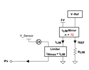
    If this is the case, I'm not sure this will work as the current need to be going out of the IPx pin and into the limiter to work. 

    If i'm off-base on my understanding, can you provide a quick drawing of what you mean?

    Thanks,
    Rami