This thread has been locked.

If you have a related question, please click the "Ask a related question" button in the top right corner. The newly created question will be automatically linked to this question.

TCAN4550: TCAN4550

Part Number: TCAN4550

Hi Jonathan,

We have applied the patch which you had shared us and have started the testing. We are using <0x0 0 0 26 0 0 1 1> as our current mram-cfg. Since the size is limited to 2K bytes, we will not be able to use the earlier configuration <0x0 3 2 32 10 1 32 7> which is exceeding 2K byes. By using the current configuration we are not observing any upgrade in the performance.

So is there any other configuration which you would suggest us?

Regards,

Akshay Naik

  • Hi Akshay,

    Since it has been awhile and the other thread got locked because of inactivity, can you remind me again on the current state of performance?  I recall there were multiple nodes trying to send and receive messages and that after some period of time one of them would stop transmitting.  Is this still correct?

    It would be helpful if you could give me a basic overview again of your observations, of what needs to be solved.  The driver was updated to improve the message throughput and be more efficient, but if you are still seeing one node go silent after a period of time then this may not be related to the driver.  Also, if this is the case, can you remind me again what that period of time is between the start of your test and when it stops working?

    Thanks,
    Jonathan

  • Hi Jonathan,

    Yes the scenario is same as you explained. 

    But I have not yet tested that scenario.

    I believe that I had shared our bosch,mram-cfg = <0x0 3 2 32 10 0 26 12> (in earlier thread) using which we were testing the scenarios. But in the updated driver, the same configuration does not seem to be working. Whenever we try to insert the TCAN module with the above configuration it shows an error "tcan4x5x spi0.0: Total size of mram config(3980) exceeds mram(2048)" and the TCAN initialisation fails. 

    So i modified the bosch,mram-cfg = <0x0 0 0 15 6 5 1 1which does not exceed the 2048 bytes and initializes the TCAN without any issues. But with this configuration the device stops receiving the data if executed more than 10 minutes, even if there is only one node transmitting the data. 

    So I was thinking if there is any other configurations which I can try out, so that my reception works with out any issues. Once that works i will move on to the other scenario which you had mentioned.

    I hope this gives you clear picture of the scenario. Kindly let me know if you need any more clarifications.

    Regards,

    Akshay Naik

  • Hi Akshay,

    I've done some calculations on the MRAM space needed for your previous configuration of bosch,mram-cfg = <0x0 3 2 32 10 0 26 12> and it looks like that should fit per my calculations.  I will have to check into this because assuming the RX and TX buffer elements are configured for a full 64-byte data payload, your previous configuration should be about 50% of the total MRAM.

    As long as the the MRAM allocation fits all the elements without overlap, and has enough elements for the processor to receive, store, and read the messages in a timely fashion, and avoid an Overflow condition, I don't know a reason why the configuration would make a difference.  If the RX FIFOs or Buffers become full and the processor can't clear them in time, new messages may be rejected. 

    Can you read back all the device registers so that we can see what the configuration, status/interrupt, and error counter registers so we can get a fresh look at what state the device is with the new version of the driver?

    I'd like to see if there are any status or interrupt bits that are getting set, or if the mode has changed, or if there are any TX/RX errors that may have caused the device to enter an error warning or Bus Off condition.  I'd also like to verify the driver is allocating your MRAM space correctly since the calculations seem to differ between the old and new version.

    Regards,

    Jonathan

  • Hi Jonathan,

    Sorry for the delay.

    I was able to change the MRAM configuration. But I'm stuck in another issue which is briefed below:

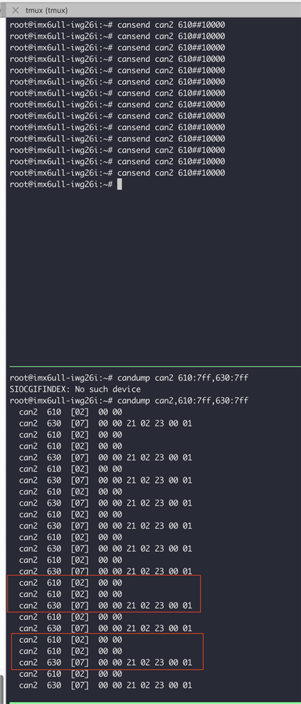
    1) The TCU is connected to the VCM(Vehicle Control Module). The TCU transmits the request frame to VCM as shown in Fig 1. Whenever the VCM receives this request, it responds back the response frame as shown in Fig1. But sometimes the responses get missed while receiving from our TCU device as shown in the Fig1. While TCU performed TX requests, I also monitored all the traffic using PEAK CANFD device, and the PEAK saw 100% of the request frames with 100% of the response frames. So, the TCU transmitted successfully, but somehow it missed the RX message right after TX sometimes.

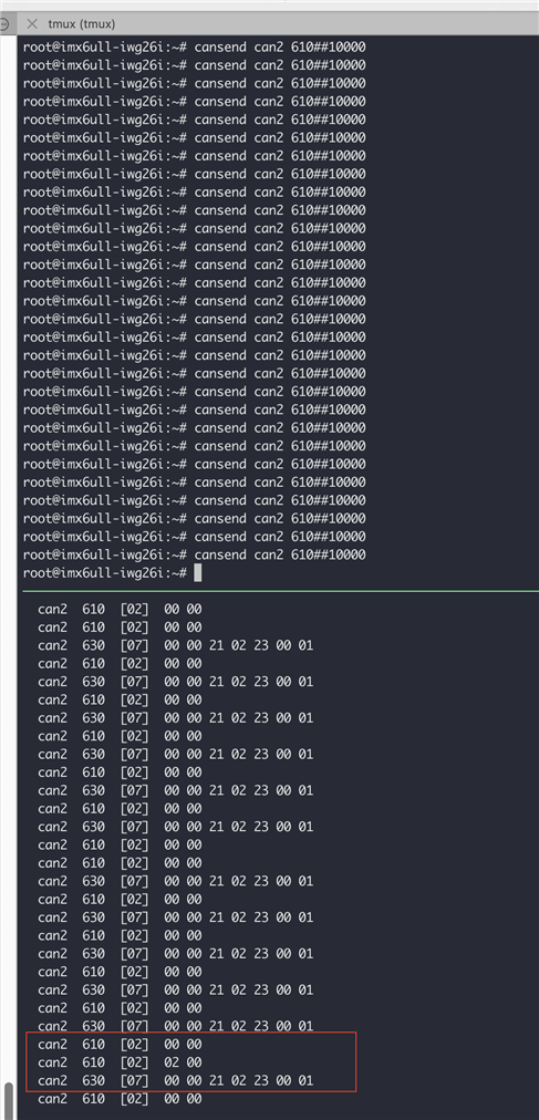
    2) Also sometimes the request message has some unknown data as shown in Fig 2. 

    Any idea on what might be causing this issue? Kindly let us know if we are missing out something.

    Regards,

    Akshay Naik

  • Hey Akshay,

    The Engineer that is supporting this issue is currently out. He be back next week to answer your questions.

    Kind Regards,

    Jack 

  • Hi Jonathan,

    While debugging on one of the issue getting unknown data, I observed that there is a Global Filter Configuration Register(GFC) where Non matching frames are accepted. We are not able to modify it since it is Write Protected. 

    Is there any way to modify this because i believe that this might solve the issue of getting unknown data.

    Thank you for your help.

    Regards,

    Akshay Naik

  • Hi Jack,

    Sure, thanks for letting me know.

    Regards,

    Akshay Naik

  • Hi Akshay,

    I apologize for the delay while I was out of the office. 

    The Protected registers are only write protected when the INIT and CCE bits are set to "0" in the Control Register h1018.

    This prevents the configuration from changing while the device is in normal mode and actively participating in CAN communication that could cause communication errors.

    To make a change to protected registers, you must first set the INIT and CCE bits to "1".  Note, this may take a couple of register Writes to set both bits because the CCE bit also requires the INIT bit to be "1" before it can also be set to "1".  So write to the control register at least 2 times with both INIT and CCE bits set to "1", then make your configuration changes to any protected registers, and then set at least the INIT bit back to "0" before resuming normal operation.

    As you have noted, rejecting any messages that do not pass your specific filter criteria will prevent them from entering the RX FIFO and should reduce the amount of interrupts and the chance for a FIFO overflow and missed messages.

    Can you let me know if you are still seeing the other issues after you have made this GFC change?

    Regards,

    Jonathan

  • Hi Jonathan,

    No problem. Jack had already informed me about your leave. 

    I will try the above method and will let you know on the status. Meanwhile our customer had reported one more issue which is mentioned below:

    The CAN2 is initialized by using the below command:

    "ip link set can2 txqueuelen 100 up type can bitrate 500000 dbitrate 2000000 fd on"

    After initializing the CAN2 if we try transmitting the data at 2ms or less than 2ms inter-frame delay, the transmission stops showing the message 

    "tcan4x5x spi0.0 can2: bus-off"

    "Write: No buffer space available"

    This happens only if we try giving the txqueuelen around 100 or less than that. But I tried giving the txqueuelen around 25000 and executed the same scenario where I did not face any issue as mentioned above and transmission happened successfully.

    Could you please guide us on what might be getting wrong?

    Regards,

    Akshay Naik

  • Hi Akshay,

    A "bus-off" condition occurs when the one of the TX or RX error counters exceeds 255 as defined in the CAN FD protocol standard.  These error frames usually indicate some sort of signal integrity issue on the bus, or a bit-timing configuration mismatch between the transmitting and receiving nodes on the bus.  

    When the device tries to transmit a message and another receiving node on the bus detects an error, that receiving node will throw and error frame which will cause the transmitting node to abort the message transmission and increase the Transmitter Error Counter (TEC).  Because this message was not successfully transmitted, the device will keep it in the FIFO/Queue and try to re-transmit it again until it is successfully transmitted and it receives an Acknowledge (ACK) from the receiving nodes. 

    Because you are also receiving a "Write: No buffer space available" message, I would interpret this as the TX buffers are full of messages waiting to transmit because this node keeps getting transmit errors which leads to the bus-off condition.

    You can check the Error Counter register 0x1040 to read the Tx and RX error counters (TEC, and REC) to see whether there are errors, and on which nodes are getting the TX errors, and which nodes are seeing the RX errors.

    I don't know how the queue length would cause a bus-off condition on it's own.  Instead, I do know how transmission errors can prevent the queue from being emptied and remain full.  I would verify the bus connections and check for the reason why there are errors such as poor signal integrity, or one of the nodes on the bus has a different bit-timing configuration, etc.

    Regards,

    Jonathan

  • Hi Jonathan,

    Thanks for briefing us on the issue.

    One of our customer is trying to execute one more scenario which is listed below:

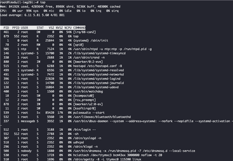
    The CAN initialization is being done on boot up using a service and during the boot(before CAN initialization) if CAN traffic is provided to the device the device hangs and sometimes it does not boot completely. When it booted completely, before hanging I checked the CPU usage by giving the "top" command and I observed that the interrupts from CAN was increasing the CPU usage(as shown in below image) because of which the performance was slowed down drastically.

    Just to add: If the same scenario is executed after booting the device, it works without any issue.

    Any idea on what might be causing this.

    Regards,

    Akshay Naik

  • Hi Akshay,

    I don't know for sure and I would have to see exactly what is happening at a register level during the boot sequence, but these are my thoughts. 

    Correct me if my understanding is incorrect, but I basically understand your question to imply that the TCAN4550 is generating interrupts during the boot sequence as a result of the CAN bus activity which is slowing down the processor and preventing the device from booting properly.

    The TCAN4550 will only participate in CAN bus activity (either by sending or receiving messages) if the INIT bit in Control register (0x1018) is set to "0" and the devices MODE_SEL bits in the Modes of Operation and Pin Configuration register (0x0800) are set to "10" for Normal Mode.  The footnotes for register 0x0800 also inform that the INIT bit is set automatically when the MODE_SEL bits change.

    The device's MCAN configuration registers such as the bit timing and MRAM allocations require the INIT bit to be set to "1" so the MODE_SEL field should be set to "01" for "Standby Mode" until the TCAN4550 configuration is complete.  Only when the TCAN4550 has completed the configuration or boot sequence should the MODE_SEL field be set to "10" for Normal mode.

    Can you check to make sure the MODE_SEL field stays in Standby mode for the entire boot sequence and only changes to Normal mode at the very end of the sequence?

    Regards,

    Jonathan

  • Hi Jonathan,

    Above briefing was very helpful which solved our booting issue.

    But we are facing other issues which are listed below:

    1) Hang Issue:

     When we boot the board with active traffic provided and then initialize the CANFD, it starts receiving the data. But the reception happens only for few hours(4 to 5 hrs) and then the TCU hangs again and reboots. And also we observed that the interrupt was occupying most of the CPU usage as image shared in previous thread. What might be the issue causing this?

    2) TCU hangs or  resets when disconnecting CAN Link:

    I notice that while TCU is transmitting CAN TX messages, physically disconnecting TCU from the rest of the CAN bus is causing the TCU to reset itself or hang. Any idea what might be cauing this?

    3) Missing Response:

    We are testing below scenario:

    There are 2 TCU's which are connected over CAN bus.

    • TCU1 sends 5 bytes header data with ID 0x31. TCU2 receives this data and sends response as mentioned in next point.
    • TCU1 receives 1 byte 0x79 as response of step 1 (sent by TCU2), also with ID 0x31
    • After receiving the data, TCU1 sends 4  frames of full 64 bytes/frame or 256 bytes total on ID 0x31. TCU2 receives this data and sends the response as mentioned in next point.
    • TCU1 receives 1 byte 0x79 as acknowledgement of step 3 (sent by TCU2), also with ID 0x31
    • Repeat 1-4 as fast as possible until the update is finished, this cycle can go a few thousand times for large update. If TCU sees no response in either step 2 or 4 after a few seconds, it should abort the entire process. While testing this we observe that some of the messages are being missed and cannot be seen in the candump utility. Could you please guide us on this?

    Sorry for dumping out lot of questions. Could you please help us resolve this issues as soon as possible as these are very higher priority to us?

    Regards,

    Akshay Naik

  • Hi Akshay,

    I'm glad I could be helpful in resolving your Boot issue.

    1) Hang Issue:

    The TCAN4550 can generate a lot of interrupts, particularly one for every message received.  If you are only concerned with specific message ID's you can filter out those messages allowing the device to discard any unfiltered message and reduce an interrupt from those messages. Are you using any type of message SID or XID filtering?  Is there any message traffic you can ignore in the application that is generating unwanted interrupts?

    2) TCU hangs or resets when disconnecting CAN Link:

    The only reason I can think of why any CAN FD node will remove itself from the bus is due to a high error count and the device has entered a Bus Off condition as defined in the CAN FD specification.

    3) Missing Response:

    After receiving the data, TCU1 sends 4  frames of full 64 bytes/frame or 256 bytes total on ID 0x31. TCU2 receives this data and sends the response as mentioned in next point.

    Can you clarify whether there is a response after each 64 byte frame, or only after the completion of 4 full 64 byte frames?  Basically I want to make sure I understand whether there is a response frame from TCU2 for each TCU1 frame it receives, or whether there is only a response frame from TCU2 after reception of 4 frames from TCU1.

    If there is only a response by TCU2 after receiving 4 frames from TCU1, how is this triggered?  Is there a counter in TCU2 that counts the received frames, or the total received bytes, etc.?

    When I take this question as a whole, my thoughts are that there may be some error frames that eventually lead to a bus off condition and or missed data. Or there could be a bug in how the total received data is counted and acknowledged that leads to some situation where the TCU's are no longer communicating such as one TCU thinks the data is complete, and the other is waiting for more data to come and trigger the abort sequence you mentioned.  I'm only speculating.

    Is there a way to monitor the CAN bus error counters to see if there is some incremental error count that eventually leads to a bus off condition?

    Is there a way to verify the TCU2 node receives the proper bytes before acknowledging?

    Regards,

    Jonathan

  • Hi Jonathan,

    Please find my highlighted response:

    1) Hang Issue:

    Are you using any type of message SID or XID filtering?  Is there any message traffic you can ignore in the application that is generating unwanted interrupts?

    We are not using any SID or XID filtering currently. We are just reading out all the messages which are on the CAN bus.

    2) TCU hangs or resets when disconnecting CAN Link:

    I'll check on this and will let you know on the status.

    3) Missing response 

    Can you clarify whether there is a response after each 64 byte frame, or only after the completion of 4 full 64 byte frames?If there is only a response by TCU2 after receiving 4 frames from TCU1, how is this triggered?  Is there a counter in TCU2 that counts the received frames, or the total received bytes, etc.?

    The response is after receiving 4 full 64 byte frames. We have developed an application which handles this.

    Is there a way to monitor the CAN bus error counters to see if there is some incremental error count that eventually leads to a bus off condition?

    Yes we have a PCAN simulator using which we can keep track of the error count.

    Please let me know if you need any more information.

    Regards,

    Akshay Naik

  • Hi Akshay,

    If there is additional traffic on the bus you don't care about, you may want to create message filters to reduce unwanted interrupts and free up the processor load.

    Outside of verifying the error counts and checking the correct number of bytes and frames have been received, I don't know what else to recommend to look at from a TCAN4550 device level. 

    Regards,

    Jonathan

  • Hi Jonathan,

    Thanks for the suggestion. Will try creating the message filters and test the scenario.

    I had one more query which is listed below:

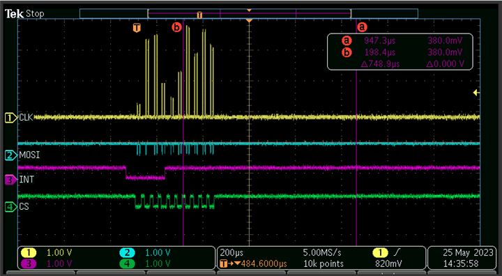
    We have added timestamp reading inside spi driver then we observed that delay of ~0.9 ms between each transfer.

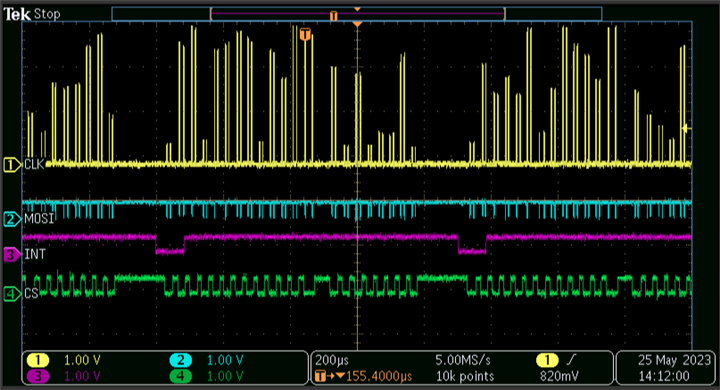
    We probed the CS, CLK, MOSI and interrupt pin. On probing we observed that interrupt is happening on every 0.8 ms and the gap between 2 continuous CS low & high is 0.9 ms (Not between single CS low & high, you can see a stream of CS line going low and high then there is a long gap). We are able to receive data in the reception side also on every 0.9 ms. Multiple no. of clocks also triggering at the same time. Please see below trace.

    Even after triggering multiple clock, CS pin, I was able to receive 1 data at reception side and interrupt is holding high for a long time. Is that expected interrupt holding high for a long duration?

    We observed that 4 byte data is transferring while CS going low and high. Is it possible to transfer more than 4 bytes on a single CS going low & high.

    One more interesting thing we observed is without transferring any data, We are getting pulses from the probed lines CS, interrupt, clock. Below is the trace for that.

    Could you please let us know what might be going wrong here?

    Regards,

    Akshay Naik

  • HI Akshay,

    Even after triggering multiple clock, CS pin, I was able to receive 1 data at reception side and interrupt is holding high for a long time. Is that expected interrupt holding high for a long duration?

    The interrupt pin will be released once all the bits have been cleared through SPI writes.  Depending on how the ISR routine is handling this, it could cause the interrupt line to be held low as shown. I see the CS toggles Low 2 to 3 times while the interrupt line is low which could account for a SPI Read of the Status and Interrupt registers, and then a SPI Write to clear the set bits.  A more detailed analysis of what SPI communication is happening while the interrupt pin is low would be needed and could be more easily performed by connecting a logic analyzer to these pins to decode the data.

    I think the interrupt line is likely being held low until all the SPI Reads and Writes required to clear the interrupts are completed.

    We observed that 4 byte data is transferring while CS going low and high. Is it possible to transfer more than 4 bytes on a single CS going low & high.

    Yes, the TCAN4550 supports multi-word SPI transfers for consecutive register addresses and MRAM memory locations such as a RX or TX buffer.  This reduces the need to send an address for each word of data (or 4 bytes) that needs to be transferred and can greatly improve the efficiency.  This is done by setting the "LENGTH" field of the SPI sequence to the number of data words that need to be transferred.  The Read and Write figures in the datasheet show this by using examples where the Length field is set to 2 and a total of 8 data bytes are transferred while the CS line is low.  To be clear the Length field is for the length of data words that need to be transferred and does not include the word of data that has the Read/Write Op Code and Address and Length fields.

    Therefore, you can set the Length field to match the total length of the CAN message, or consecutive registers that need to be read or written to, and just provide the starting address for the first register or MRAM location that corresponds with the first word of data you will be sending.

    If the number of bits (SPI clock cycles) do not match the number of bits that are expected based on the Length field, then the TCAN4550 will throw a SPI Error.

    One more interesting thing we observed is without transferring any data, We are getting pulses from the probed lines CS, interrupt, clock. Below is the trace for that.

    Could the "pulses" you refer to be cross talk coupling from other signals routed adjacent to the pins you are monitoring?  I would need to see more zoomed in waveforms to comment further.  Since your scope is set to capture multiple CS cycles, it may not have the resolution to monitor the waveforms on a bit level and there could also be some sampling or aliasing issues at this scope configuration.  I would suggest also looking at the waveforms with a smaller horizontal resolution (zoomed in) configuration to get a better look at whether the pulses you are seeing.

    Regards,

    Jonathan

  • Hi Jonathan,

    Thank you for the info.

    Is it possible for you to give us a brief explaination on the flow of TCAN wrt SPI?

    Any documentation would also be helpful.

    Regards,

    Akshay Naik

  • Hi Akshay,

    We have a TCAN45xx Software User's Guide that contains the overall operation and configuration of the device.  It also contains some step-by-step examples of how to send and receive a CAN message.  This is intended to help explain the device with a bare-metal coding application in mind, so it has fairly good overview of the SPI flow needed to operate the device.  I would start with recommending this document.

    Regards,

    Jonathan

  • Hi Jonathan,

    Thanks for the information. It will help us a lot.

    We had downloaded the m_can driver from below github link:

    Github link : github.com/.../m_can

    After integrating this driver, while running this driver we are facing the segmentation fault issue. Could you please let us know what might be going wrong?

    Regards,

    Akshay Naik

  • Hi Akshay,

    Unfortunately I am not a Linux developer and my expertise is with the TCAN4550 at a device level.  I can help with questions about the device configuration settings, but I'm not going to be able to help much with the driver itself.

    The TCAN4550 essentially integrates the M_CAN IP with a CAN FD Transceiver and then wraps all of this with a SPI interface.  Some of the SPI registers pass directly through to the M_CAN, and other registers for the rest of the TCAN4550 such as the Transceiver mode control, status and interrupts, etc.

    It is my understanding that the existing tcan4x5x linux driver was built essentially in the same way and wraps the M_CAN driver with the additional SPI registers needed for total control of the device.  There were also some recent revision work that was done on this driver to improve the efficiency.

    Regards,

    Jonathan

  • Hi Jonathan,

    Thank you for the quick reply. 

    Could you please let us know where we can post m_can related doubts? Is there any kind of support mechanism, where we can post queries related to m_can?

    Regards,

    Akshay Naik

  • Hi Akshay,

    The m_can driver is upstreamed into the Linux Kernel and therefore it is supported by the Linux community.  Since I'm not a Linux developer, I don't know where to direct you for this type of support and I'm not familiar with any Linux support forums.

    However if your questions are more related to how the M_CAN IP needs to be configured or how it operated from a conceptual level, I can still help you with those types of questions.  I just can't offer much help on the Linux m_can driver itself.

    Regards,

    Jonathan

  • Hi Jonathan,

    We are very grateful for your help.

    I had one more query which is listed below:

    • We have disabled the loopback & local echo support from the MCAN driver. After onwards we are getting Protocol Error in Data Phase Enable while the end node not connected to TCAN. Is that expected? Is this error related to loopback or echo?

    Regards,

    Akshay Naik

  • Hi Akshay,

    This is likely because there is no additional node on the CAN bus to "acknowledge" the message that is being transmitted.  When the controller is in "loopback" mode, mcan treats its own transmitted messages as received messages and ignores acknowledge errors.

    Regards,

    Jonathan

  • Hi Jonathan,

    That was very helpful.

    We are facing an issue of response getting missed. The scenario is explained below:

    We connected the PCAN to TCU and from PCAN we transmitted 10000 data to TCU. But TCU was able to receive only around 7000 data. Rest of the data is getting missed. Any idea what might be going wrong?

    Regards,

    Akshay Naik

  • Hi Akshay,

    I can think of a few ideas to check.

    • Message rate is too fast for the processor to clear the new messages resulting a RX FIFO or Buffer Overflow scenario which leads to discarded messages
      • This is probably the most likely event.  Try to increase and reduce to message transmission frequency to see if the number of received messages increases and decreases respectively.  Also if you are using a RX FIFO, you can monitor the RF0L or RF1L bits in the Interrupt register to see if a message was lost.
    • Messages are generating error frames due to a protocol or signal integrity error
      • This should result in a re-transmission attempt for the message unless the automatic re-transmission feature has been disabled with the DAR bit.  You can monitor the Transmit and Receive Error counters (TEC and REC) in the Error Counter Register.
    • Messages are getting filtered
      • If you are using any type of message filtering, make sure the transmitted messages contain IDs that will pass the receiver's filters.

    Regards,

    Jonathan

  • Hi Jonathan,

    Thanks for the information. It was very helpful.

    I'm facing issue in 64bytes data reception. I observe that CAN received messages are getting missed. 

    This scenario is observed only while receiving 64 bytes of data. If i try to receive 8 bytes of data, there is no issue.

    The reception for 8 bytes was tested for more than 14hrs and I did not observe a missing response. But when i try just receiving 64bytes data i observe that responses are getting missed.

    Could you please guide me on what might be missing?

    Regards,

    Akshay Naik

  • Hi Akshay,

    So if I understand you correctly, you are only receiving 70% of the messages when you have a 64byte data payload.  Is that correct?

    We connected the PCAN to TCU and from PCAN we transmitted 10000 data to TCU. But TCU was able to receive only around 7000 data. Rest of the data is getting missed. Any idea what might be going wrong?

    If my understanding is correct, then I can only think that the interval between the CAN message transmission is slightly too fast.  It takes longer to transfer 64bytes of data between the TCAN4550 to the processor through SPI than it does 8 bytes.  This will cause the device to take longer to acknowledge the message in the RX FIFO which could lead to a RX FIFO Overflow condition and a lost message.

    Are you monitoring the RF0L or RF1L bits in the Interrupt register to see if a message was lost?  If you have set a watermark fill level the RF0W or RF1W will get set.  Also, the RF0F and RF1F bits should reflect a full RX FIFO.  All of these bits will be an indication that messages are being received faster than can be processed.

    Are you able to adjust the time interval between CAN messages?  If so, doe it make any difference, i.e. does increasing the delay between message transmissions cause fewer messages to be lost?  Or do you still see the same amount of lost messages regardless of the transmission interval?

    If you don't see any RX FIFO level related interrupt bits, and timing does not change the results, then there may be some other configuration issue to explain the reason for missing 30% of the 64byte messages.

    Also, are the messages in your test all the same (i.e. same ID and Data length/value), or are they of different IDs, data lengths and values?

    Regards,

    Jonathan